
revision date: 2026.04.28
FOREWORD
Thank you for purchasing our Force Torque sensor. This manual contains the information necessary for the correct use of the AIDIN ROBOTICS AFT200-D80 sensor.
Please carefully read this manual when using this software.
Please note that the basic performance of the product will not be exhibited when the robot system is used out of conditions.
This manual describes possible dangers and consequences using Force Torque sensor. Be sure to comply with safety precautions written in this manual to use safety and correctly.
NOTICE
This manual Do NOT allow copy, reproduction or share without authorization of AIDIN ROBOTICS.
Please notify us any errors in this manual or the provided instructions.
MANUFACTURER
AIDIN ROBOTICS
SAFETY PRECAUTIONS
Installation of Force Torque sensor MUST be performed by qualified personnel in accordance with national and local codes. Please carefully read this manual when using this software.
WARNING & CAUTION
This symbol indicates that a danger of possible serious injury or death exists if the associated instructions are not followed properly.
This symbol indicates that a danger of possible harm to people or physical damage to equipment and facilities exists if the associated instructions are not followed properly.
AFT200-D80-C sensor from AIDIN ROBOTICS meets CE-certified “A Class”
1. Introduction
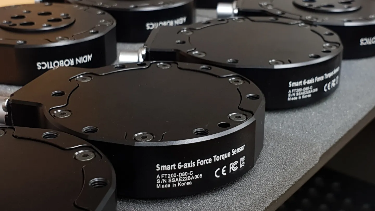
1.1 Smart 6-axis Force Torque Sensor, AFT200-D80
1.2 Key features
•
Smart 6-axis force/torque sensor
•
All-in-one sensor (No additional amplifier)
•
Digital output communications (CAN)
•
Easy installation and data collection
•
Grippers, robot hands, collaborative robot, industrial robot
1.3 Specs.
Index | Unit | Value |
Operating voltage | VDC | 5 |
Max. safe excitation voltage | VDC | 12 |
Nominal force range | N | 200 |
Nominal torque range | Nm | 15 |
Limit force (Fxyz) | N | 300 |
Limit torque | Nm | 22.5 |
Force Resolution | N | 0.15 |
Torque Resolution | Nm | 0.015 |
Force Noise-free resolution (STD) | N | 0.4 |
Torque Noise-free resolution (STD) | Nm | 0.025 |
Maximum sample rate | Hz | 1,000 |
Dimensions | mm | D80 x H21.5 |
IP rating | IP56 | |
Operating temperature | 10-50℃ |
1.4 Flyer
2. Installation Guide
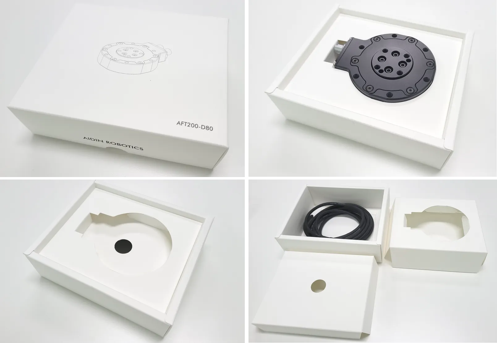
2.1 Basic Components
•
AFT200-D80 x 1 EA
•
3m Cable x 1 EA
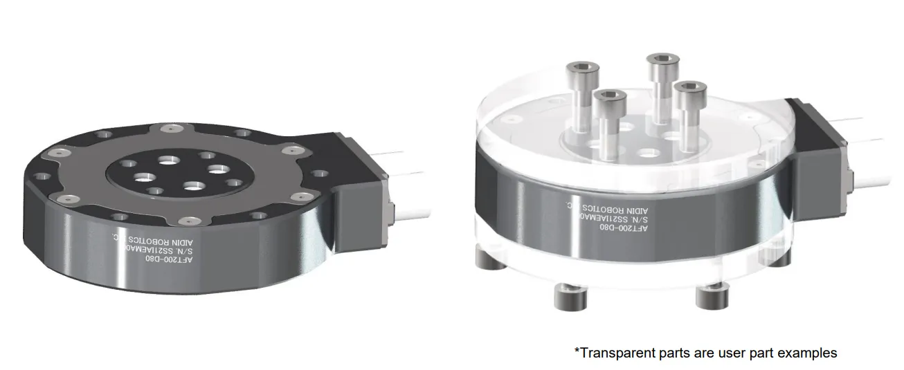
2.2 Mounting
•
M5 bolt 5.2Nm required for tightening
•
Performance cannot be guaranteed and A/S not possible when disassembling internal/external bolts
•
Sensor tightening order
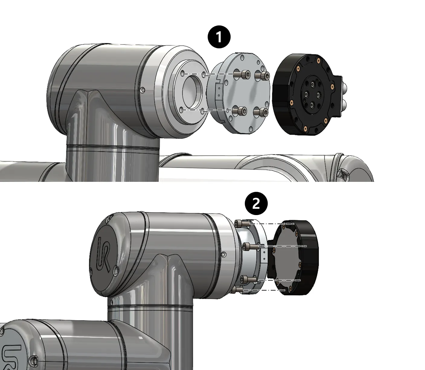
•
CAUTION OF CABLE CUTTING AND EXCESS PULLING
•
Secure the sensor line with the robot so that it does not pull as it moves
◦
Do not fix it to the robot using cable ties, etc., or use cable ties to fix it in a bundle shape like other wires
◦
We recommend that you use Velcro to fix it with the robot, and please use Velcro to fix it when fixing it in a bundle form with other lines
Performance CANNOT be guaranteed if not followed to the tightening torque guide.
If the sensor line is not fixed to the robot, the output signal may have a noise due to the pulled by robot
Please check More detail setup guide as follow:
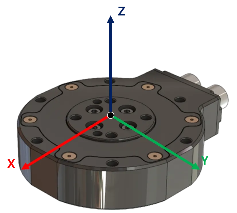
2.3 AXIS & Drawings
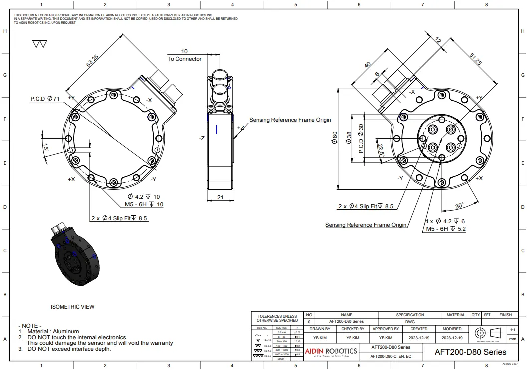
Drawing File :
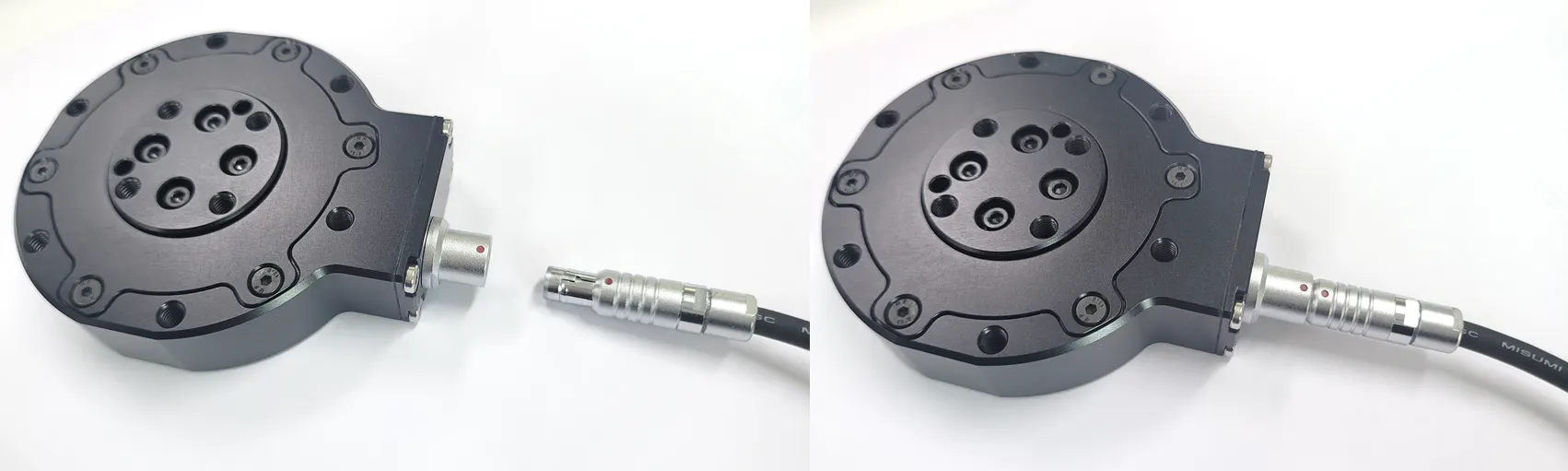
Port Location Notice
•
EtherCAT Type model has two ports: IN and OUT.
•
Ethernet Type model has one port, located on the left side.
•
CAN Type model has one port, located on the right side.
STEP File:
2.4 Wiring
2.4.1 Pin out
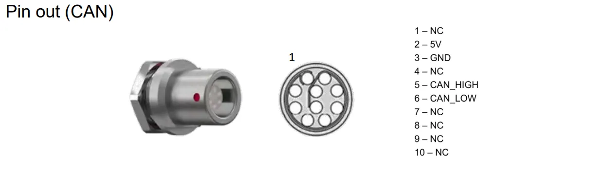
2.4.2 Cable open-end
•
Cable pin out
◦
Length: 3m
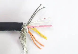
◦
5V(VCC) - Orange, Black dot
◦
GND - Gray, Black dot
◦
CANH- Yellow, Black dot
◦
CANL - Pink, Black dot
Other pins are not using
◦
Connection PCB Installation Guide
▪
Insert the lines as illustrated below and fasten the bolts on the terminals.
▪
Each connection point is indicated on the PCB connection point, and the sequence is as follows:
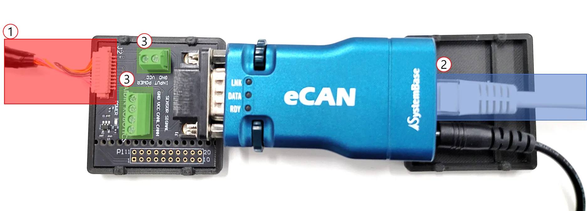
1.
Sensor Connector (Connector section connecting to the sensor)
2.
EtherNET Connector (Connector section connecting to the PC)
3.
Sensor Connector
a.
Upper 2-port terminal block: VCC, GND
b.
Lower 4-port terminal block: VCC, GND, CAN High, CAN Low (Optional)
▪
VCC and GND should be connected to a power supply device providing stable 5V.
▪
The 9-pin D-sub is connected to the eCAN device.
We recommend using an approved power supply device.
2.4 Default Data Output Rate
•
The output rate can be changed from 100 Hz to 1000 Hz
•
Please refer to the “2.5 Mode setting” below for how to change it

2.5 Mode setting
To stabilize the sensor signal, it is recommended to have a running time of about 30 minutes.
* Please leave the sensor data on for at least 10 minutes before using it
The first 10 minutes of sensor output data can cause data to flow.
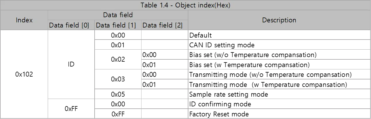
2.5.1 MODE SETTINGs
CAN ID Setting mode
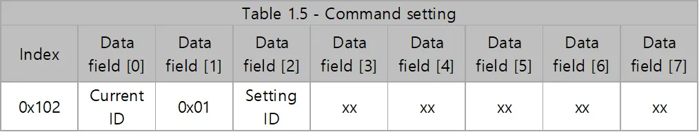
•
Data field [0] : Current Set ID (Factory Setting 0x01)
•
Data field [2] : User setting ID for transmit
Bias Setting mode
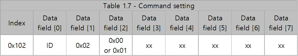
•
Data field [2] : 0x00 : Bias setting without temperature compensation (This commend should be used with transmitting mode(without temperature compensation) command)
•
Data field [2] : 0x01: Bias setting with temperature compensation (This commend should be used with transmitting mode(with temperature compensation) command)
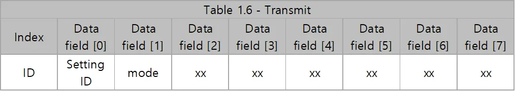
Continuous transmitting mode

•
Data field [2] : 0x00 : Transmitting mode without temperature compensation (This commend should be used with Bias setting(without temperature compensation) command)
•
Data field [2] : 0x01: Transmitting mode with temperature compensation (This commend should be used with Bias setting(with temperature compensation) command)
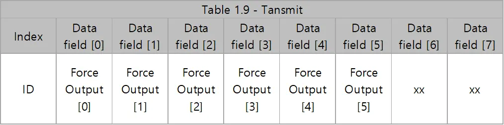
•
Fx Output = Force Output [0]*256 + Force Output[1]
•
Fy Output = Force Output [2]*256 + Force Output[3]
•
Fz Output = Force Output [4]*256 + Force Output[5]
•
Force[N] = Force Output/100-300

•
Tx Output = Torque Output [0]*256 + Torque Output[1]
•
Ty Output = Torque Output [2]*256 + Torque Output[3]
•
Tz Output = Torque Output [4]*256 + Torque Output[5]
•
Torque[Nm] = Force Output/500-50
Sample rate setting mode
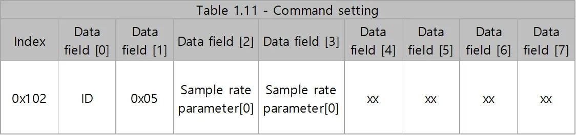
•
Data field [2] : Sample rate parameter [0]
•
Data field [3] : Sample rate parameter [1]
•
Sample rate parameter = Sample rate parameter [0] * 256 + Sample rate parameter [1]
•
Sample rate = (1,000,000/Sample rate parameter)
ex) 1000Hz, Sample rate parameter [0] = 0x03, Sample rate parameter [1] = 0xE8
ex) 500Hz, Sample rate parameter [0] = 0x07, Sample rate parameter [1] = 0xD0
ex) 333Hz, Sample rate parameter [0] = 0x0B, Sample rate parameter [1] = 0xB8
ex) 200Hz, Sample rate parameter [0] = 0x13, Sample rate parameter [1] = 0x88
ex) 100Hz, Sample rate parameter [0] = 0x27, Sample rate parameter [1] = 0x10
ID Confirming mode


Factory Reset mode

2.5.2 DEVICES
USB-to-CAN Device
•
You may use a different CAN-enabled board, but use IXXAT's converter to use the sample program
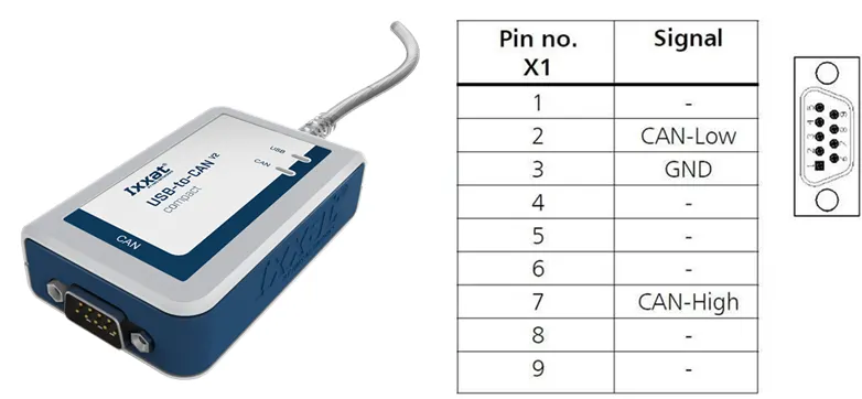
Downloads and Documentation for Ixxat Products, VCI V4 - Windows 11, 10, 8, 7 [Driver, canAnalyser-Mini, Manuals, LabView and other add-ons]*
•
Ixxat VCI Setup 4.0.xxx.0.exe
•
VCI V4 check during installation and reboot after installation
EtherNET-to-CAN Device
•
Using Systembase's eCAN model
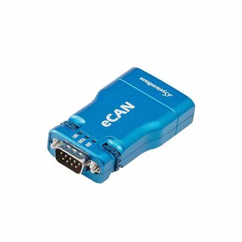
•
Download Manual and eCANView from the following site:
2.6 Force/Torque Out of Range
The sensor can operate up to its nominal capacity, while a single axis load. On Nominal capacity reading is incorrect and invalid.
The nominal capacity of composite loading is The following diagram illustrates a complex loading scenario. The sensor cannot operate outside the normal operating area
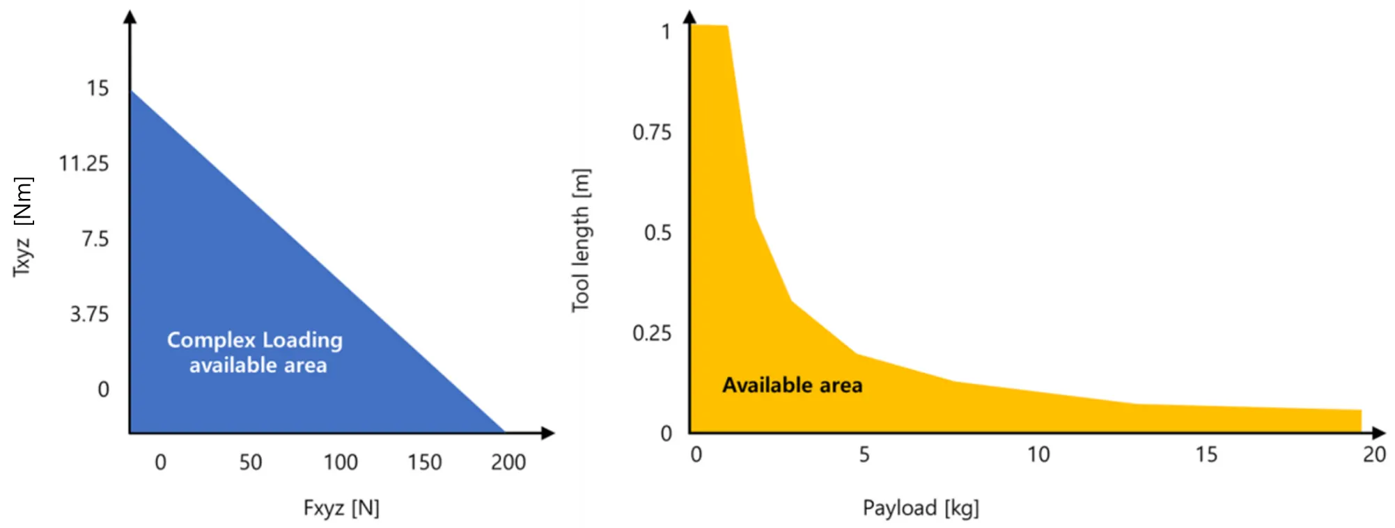
The following graph shows the range of payloads and tool lengths that can be used with AFT200-D80-C sensor for applications requiring high or moderate precision.
• The total percentage of the calibrated range used by Fxy and Tz axes is greater than 105%. Refer to the following Fxy, Tz equation.
• The total percentage of the calibrated range used by Fz and Txy axes is greater than 105%. Refer to the following Fz, Txy equation.
3. Software
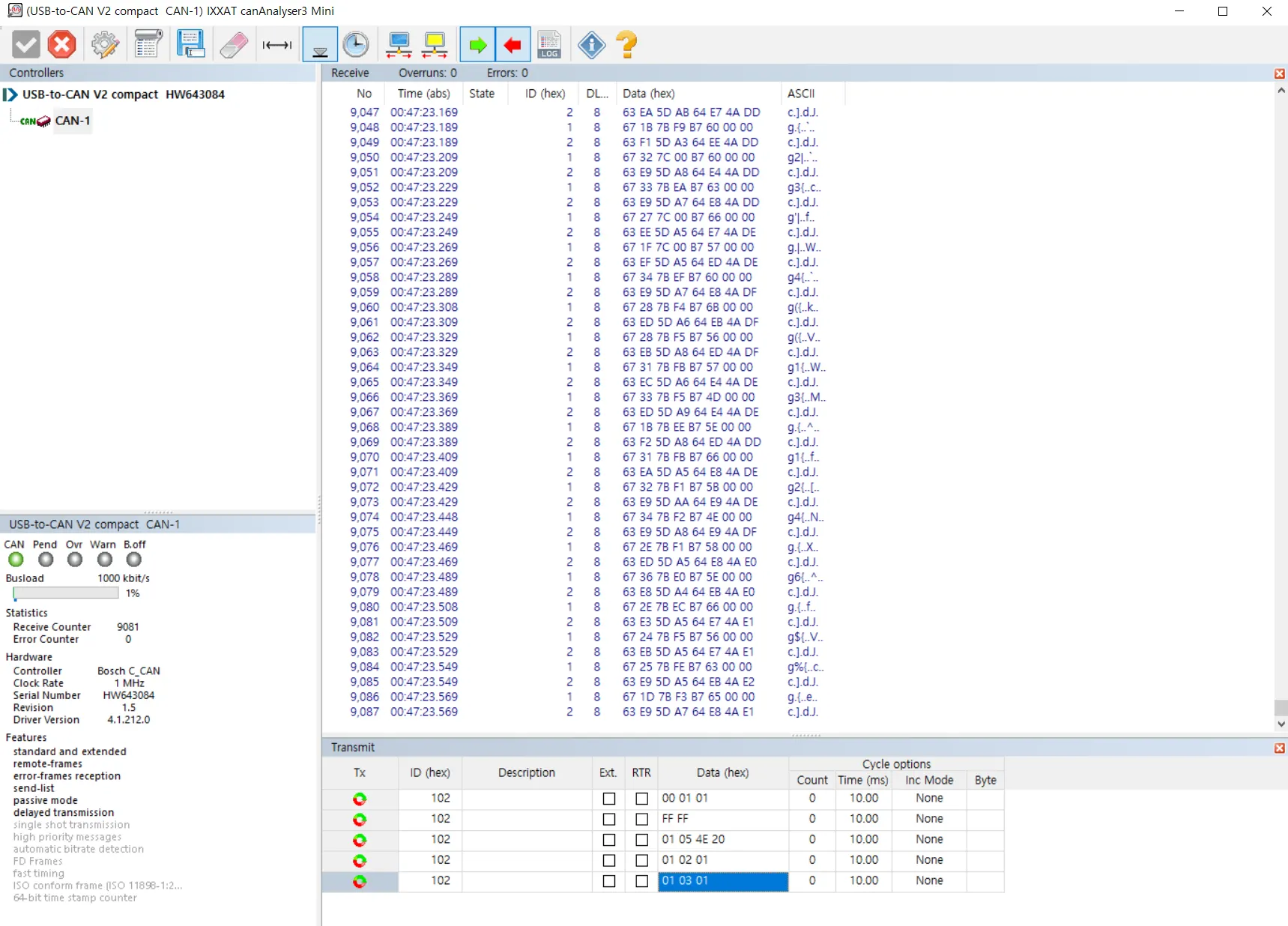
3.1.1 IXXAT’s USB-to-CAN
•
Sample Program (Provided by IXXAT)
◦
CanAnalyzer3 Mini
windows → IXXAT folder → IXXAT CanAnalyzer3 Mini
•
A sample program provided by AIDIN ROBOTICS
◦
Install IXXAT CAN VCI V4 & installer below
◦
Sample program
◦
Run AFT SERIES SAMPLE.exe after installation
•
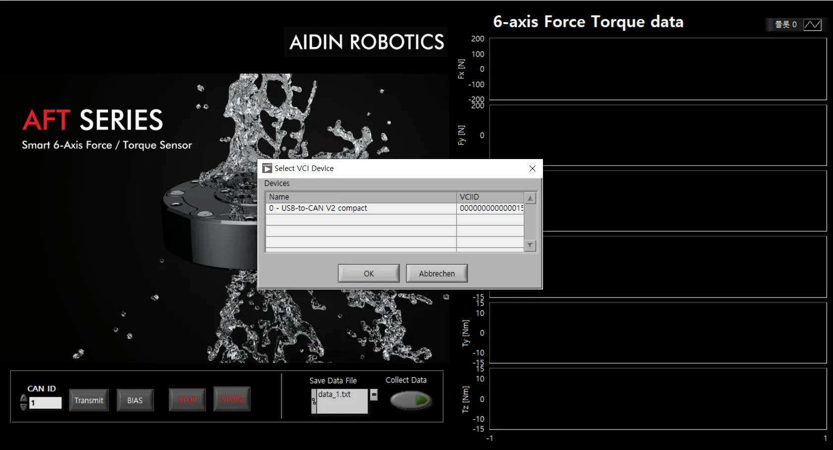
Pop-up screen when running a sample program
1.
CAN Device Selection
Select a device. Devices currently connected to your PC appear as a list. Click the appropriate device and press the OK button.
※ The sample program is based on IXXAT's USB-to-CAN converter.
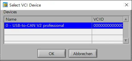
2.
CAN CONTROLLER SELECTION
Displays the device name selected in the previous step. Select the controller channel below and press the OK button.

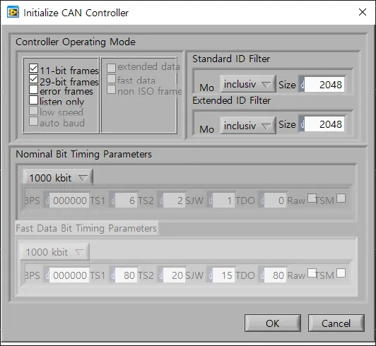
3.
CAN Controller Initial Setup
Steps to initialize the controller selected in the previous step. Check the frame and baud rate and press the OK button.
•
Sample Program Interface Description
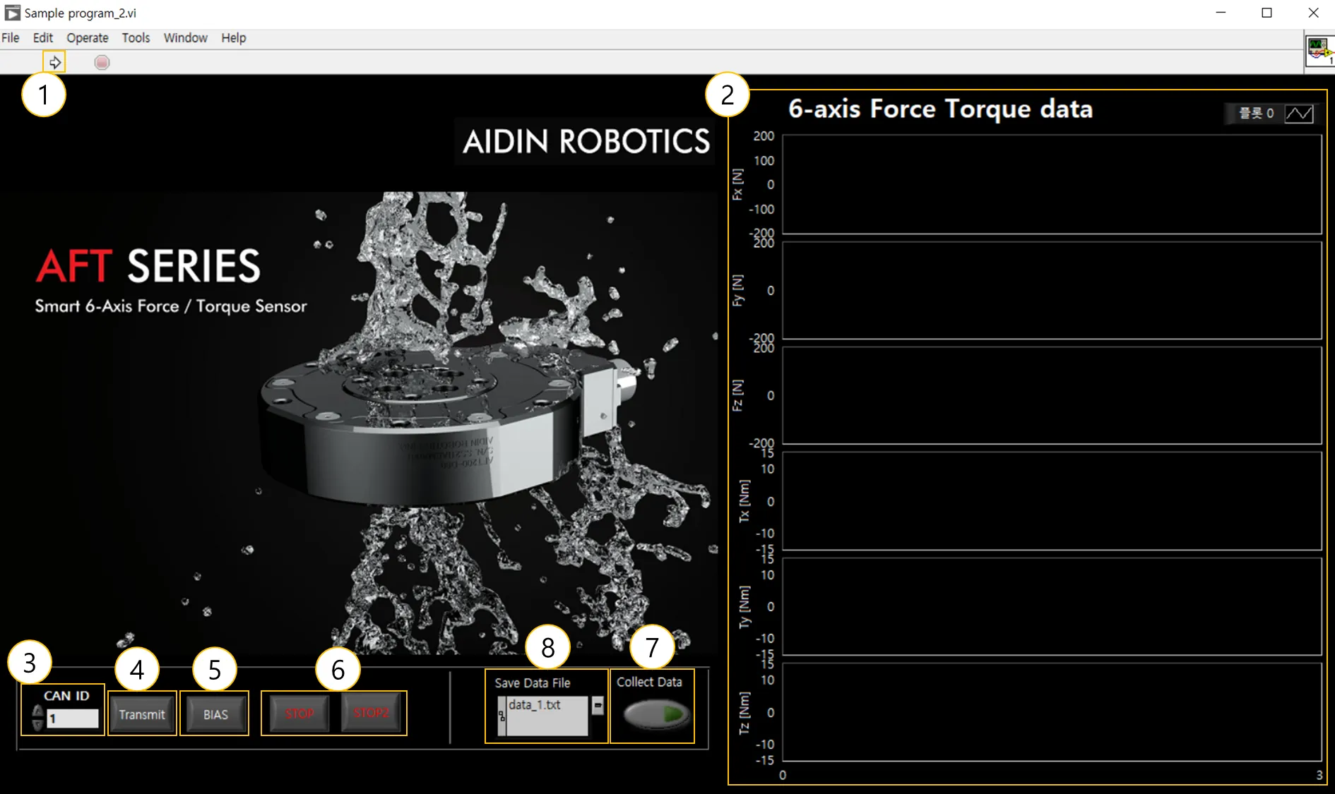
① Program run
Run the sample program.
② Graph plot
Real-time data of 6-axis force/torque data (Fx, Fy, Fz, Tx, Ty, Tz) can be viewed in a graph.
③ CAN ID
Sets the CAN ID of the connected sensor. If you have more than one ID, enter the lowest ID. ex) For 0x01(1), 0x02(2), enter 1
④ CAN transmit
Send CAN message to output 6-axis force/torque value. CAN Msg [0x102, 0x01, 0x03, 0x01]
⑤ BIAS
Initializes all 6-axis force/torque data to zero.
⑥STOP
Exit the program. Press both STOP buttons and the program will exit after 3 seconds.
⑦ Collect Data
Save the force/torque data log. Please refer to the description of data storage on the page below.
⑧ Save Data File Path
Sets the path for storing force/torque data logs. Please refer to the description of data storage on the page below.
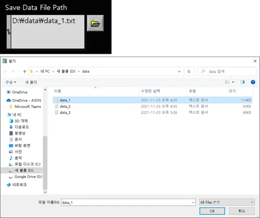
3.1.2 Save data log
1.
Save Directory Settings
Touch the folder button to open a pop-up window. Select a file (.txt) in the desired directory and press the OK button to specify it. Check the path shown in Path. (If the specified file does not exist in that path, create the file automatically)
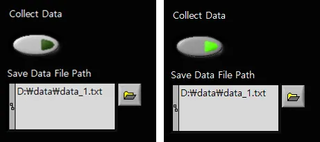
2.
Saving the Data Log
Press the button under Collect Data to start saving. When saving, the button displays a fluorescent color. Press the button to exit the save. Data is stored cumulatively in a file, so it is recommended that you specify a new file for each save.
3.
Checking the Data Log
You can open a file in that directory to view the stored force/torque data. The data are stored in each column in the order Fx, Fy, Fz, Tx, Ty, and Tz.

3.2.1 SystemBase’s EtherNET to CAN
•
A sample program provided by AIDIN ROBOTICS
◦
AIDIN_Installer→Volume→setup , Install setup
◦
Set IP through Systembase's manual or the document below
◦
Run AIDIN_Sample_EN→AIDIN_Sample_EN.exe
•
Pop-up screen when running a sample program
•
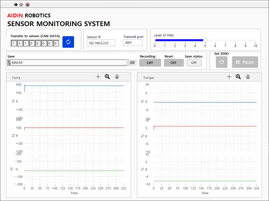
Sample Program Interface Description
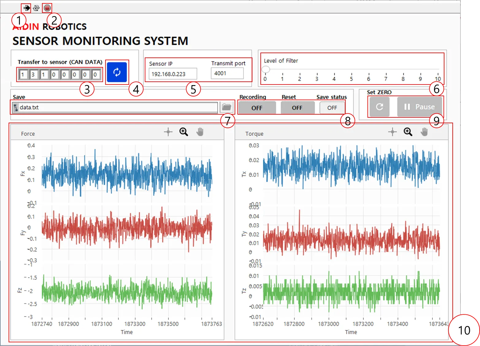
① Program run
Run the sample program.
② STOP
Exit the program. Press both STOP buttons and the program will exit after 3 seconds.
③ CAN transmit message
CAN Msg [0x102, 0x01, 0x03, 0x01]
④ CAN transmit button
Send CAN message to output 6-axis force/torque value.
⑤ IP Setting
Enter the IP of the sensor matched in the above setting
⑥ Filtering
Default LPF filter configured, available from 0 to 9.9 (10 is not available)
⑦ Save Data File Path
Sets the path for storing force/torque data logs. Please refer to the description of data storage on the page below.
⑧ Collect Data
Save the force/torque data log. Please refer to the description of data storage on the page below.
⑨ BIAS, PAUSE
Initializes all 6-axis force/torque data to zero. You can measure the desired force value by removing elements from the installation and attachment.
When you click the PAUSE button, you can pause the sensor data value.
⑩ Graph
Real-time data of 6-axis force/torque data (Fx, Fy, Fz, Tx, Ty, Tz) can be viewed in a graph.
3.2.2 Save Datalog

1.
Save Directory Settings
Touch the folder button to open a pop-up window. Specify the file (.txt) in the desired directory. Check the path shown in Path. (If the specified file does not exist in that path, create the file automatically)
2.
Saving the Data Log
Press the button below Collect Data to start saving. When saving, the button displays a fluorescent color. Press the button to exit the save. Data is stored cumulatively in a file, so it is recommended that you specify a new file for each save.
•
Initialize the data saved when you click the Reset button and start saving again
•
Please be careful with the Reset button

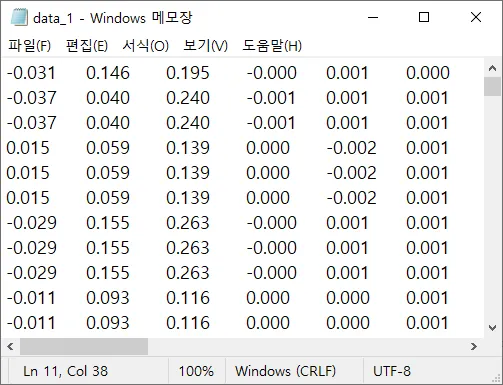
3.
Checking the Data Log
You can open a file in that directory to view the stored force/torque data. The data are stored in each column in the order Fx, Fy, Fz, Tx, Ty, and Tz.
Source codes
1.
Python code -Client
#***********************************************************************
#
# Author: AIDIN ROBOTICS <info@aidinrobotics.com>
# Date: 12-08-2023
#
# ----------------------------------------------------------------------
#
# This program is free software; you can redistribute it and/or modify
# it under the terms of the GNU General Public License as published by
# the Free Software Foundation; either version 2 of the License, or
# (at your option) any later version.
#
# This program is distributed in the hope that it will be useful,
# but WITHOUT ANY WARRANTY;
#
#***********************************************************************/
import struct
import socket
IP_ADDR = '192.168.0.223'
PORT = 4001
CMD_TYPE_SENSOR_ID = '01'
SENSOR_TRANSMIT_TYPE_MODE = '03'
SENSOR_TRANSMIT_TYPE_SET_TEMP = '01'
s = socket.socket(socket.AF_INET, socket.SOCK_STREAM)
def main():
global s
s.settimeout(2.0)
s.connect((IP_ADDR, PORT))
sendData = '04' + '00' + '00' + '01' + '02'+ '06' + CMD_TYPE_SENSOR_ID + SENSOR_TRANSMIT_TYPE_MODE+SENSOR_TRANSMIT_TYPE_SET_TEMP
sendData = bytearray.fromhex(sendData)
s.send(sendData)
recvData = recvMsg()
#Initializing
Fx=0
Fy=0
Fz=0
Tx=0
Ty=0
Tz=0
for i in range(10000):
recvData = recvMsg()
if recvData[4]==0x01:
Fx = ((recvData[6]*256+recvData[7])/100.)-300.
Fy = ((recvData[8]*256+recvData[9])/100.)-300.
Fz = ((recvData[10]*256+recvData[11])/100.)-300.
# print("Fx : " + str(round(Fx,2)) + " " + "Fy : " + str(round(Fy,2)) + " " + "Fz : " + str(round(Fz,2)) + " ")
elif recvData[4]==0x02:
Tx = ((recvData[6]*256+recvData[7])/500.)-50.
Ty = ((recvData[8]*256+recvData[9])/500.)-50.
Tz = ((recvData[10]*256+recvData[11])/500.)-50.
# print("Tx : " + str(round(Tx,2)) + " " + "Ty : " + str(round(Ty,2)) + " " + "Tz : " + str(round(Tz,2)) + " ")
print("Fx : " + str(round(Fx,2)) + " " + "Fy : " + str(round(Fy,2)) + " " + "Fz : " + str(round(Fz,2)) + " " +"Tx : " + str(round(Tx,2)) + " " + "Ty : " + str(round(Ty,2)) + " " + "Tz : " + str(round(Tz,2)) + " ")
s.close()
def recvMsg():
recvData = bytearray(s.recv(14))
printMsg(recvData)
return recvData
def printMsg(msg):
dataStr = "DATA: "
for i in range(6, 14):
dataStr += str(msg[i]) + " "
# print(dataStr)
if __name__ == "__main__":
main()
Python
복사
2.
Window code - Client
/***********************************************************************
*
* Author: AIDIN ROBOTICS <info@aidinrobotics.com>
* Date: 12-08-2023
*
* ----------------------------------------------------------------------
*
* This program is free software; you can redistribute it and/or modify
* it under the terms of the GNU General Public License as published by
* the Free Software Foundation; either version 2 of the License, or
* (at your option) any later version.
*
* This program is distributed in the hope that it will be useful,
* but WITHOUT ANY WARRANTY;
*
************************************************************************/
//Std
#pragma comment(lib, "ws2_32.lib")
#include <iostream>
//Windows Socket
#include <winsock2.h>
#include <ws2tcpip.h>
#define IP_ADDR "192.168.0.223"
#define PORT 4001
#define CMD_TYPE_SENSOR_ID 0x01
#define SENSOR_TRANSMIT_TYPE_MODE 0x03
#define SENSOR_TRANSMIT_TYPE_SET_TEMP 0x01
void printMsg(const char *msg);
void recvMsg(char *msg);
double bytesToDouble(const char *bytes);
SOCKET socket_desc;
int main()
{
WSADATA wsadata;
int error = WSAStartup(0x0202, &wsadata);
if (wsadata.wVersion != 0x0202)
{
WSACleanup(); //Clean up Winsock
return false;
}
socket_desc = socket(AF_INET, SOCK_STREAM, IPPROTO_TCP);
if (socket_desc < 0)
std::cout << "error opening socket" << std::endl;
struct sockaddr_in server;
server.sin_addr.s_addr = inet_addr(IP_ADDR);
server.sin_family = AF_INET;
server.sin_port = htons(PORT);
std::cout << "Connecting..." << std::endl;
if(error = connect(socket_desc , (SOCKADDR*)&server , sizeof(server))) {
std::cout << "Error code: " << error << std::endl;
return 1;
}
std::cout << "Connected to the AFT200-D80 Module" << std::endl;
char recvData[50] = {0};
char sendData[10] = {0};
sendData[0] = 0x04;
sendData[1] = 0x00;
sendData[2] = 0x00;
sendData[3] = 0x01;
sendData[4] = 0x02;
sendData[5] = 0x06;
sendData[6] = CMD_TYPE_SENSOR_ID;
sendData[7] = SENSOR_TRANSMIT_TYPE_MODE;
sendData[8] = SENSOR_TRANSMIT_TYPE_SET_TEMP;
send(socket_desc, sendData, 10, 0);
recvMsg(recvData);
double Fx, Fy, Fz, Tx, Ty, Tz;
for(size_t i = 0; i < 10000; ++i) {
recvMsg(recvData);
if(recvData[4]==0x01){
Fx = ((recvData[6]*256+recvData[7])/100.)-300.;
Fy = ((recvData[8]*256+recvData[9])/100.)-300.;
Fz = ((recvData[10]*256+recvData[11])/100.)-300.;
}
else if(recvData[4]==0x02){
Tx = ((recvData[6]*256+recvData[7])/500.)-50.;
Ty = ((recvData[8]*256+recvData[9])/500.)-50.;
Tz = ((recvData[10]*256+recvData[11])/500.)-50.;
}
std::cout << Fx << " " << Fy << " " << Fz << " " << Tx << " " << Ty << " " << Tz << std::endl;
}
closesocket(socket_desc);
return 0;
}
void recvMsg(char *msg) {
size_t received = recv(socket_desc, msg, 14, 0);
printMsg(msg);
}
void printMsg(const char *msg)
{
for(size_t i = 6; i < 14; ++i) {
//std::cout << (int)msg[i] << " ";
}
//std::cout << std::endl << std::endl;
};
C++
복사
3.
Linux -Client
/***********************************************************************
*
* Author: AIDIN ROBOTICS <info@aidinrobotics.com>
* Date: 12-08-2023
*
* ----------------------------------------------------------------------
*
* This program is free software; you can redistribute it and/or modify
* it under the terms of the GNU General Public License as published by
* the Free Software Foundation; either version 2 of the License, or
* (at your option) any later version.
*
* This program is distributed in the hope that it will be useful,
* but WITHOUT ANY WARRANTY;
*
************************************************************************/
//Std
#include <iostream>
//Linux Socket
#include <sys/socket.h>
#include <arpa/inet.h>
#include <unistd.h>
#define IP_ADDR "192.168.0.223"
#define PORT 4001
#define CMD_TYPE_SENSOR_ID 0x01
#define SENSOR_TRANSMIT_TYPE_MODE 0x03
#define SENSOR_TRANSMIT_TYPE_SET_TEMP 0x01
void printMsg(const char *msg);
void recvMsg(char *msg);
double bytesToDouble(const char *bytes);
int socket_desc;
int main()
{
socket_desc = socket(AF_INET, SOCK_STREAM, 0);
struct sockaddr_in server;
server.sin_addr.s_addr = inet_addr(IP_ADDR);
server.sin_family = AF_INET;
server.sin_port = htons(PORT);
if(connect(socket_desc , (struct sockaddr *)&server , sizeof(server)) < 0) {
return 1;
}
std::cout << "Connected to the CANToEth Module" << std::endl;
char recvData[50] = {0};
char sendData[10] = {0};
sendData[0] = 0x04;
sendData[1] = 0x00;
sendData[2] = 0x00;
sendData[3] = 0x01;
sendData[4] = 0x02;
sendData[5] = 0x06;
sendData[6] = CMD_TYPE_SENSOR_ID;
sendData[7] = SENSOR_TRANSMIT_TYPE_MODE;
sendData[8] = SENSOR_TRANSMIT_TYPE_SET_TEMP;
send(socket_desc, sendData, 10, 0);
recvMsg(recvData);
double Fx, Fy, Fz, Tx, Ty, Tz;
for(size_t i = 0; i < 10000; ++i) {
recvMsg(recvData);
if(recvData[4]==0x01){
Fx = ((recvData[6]*256+recvData[7])/100.)-300.;
Fy = ((recvData[8]*256+recvData[9])/100.)-300.;
Fz = ((recvData[10]*256+recvData[11])/100.)-300.;
}
else if(recvData[4]==0x02){
Tx = ((recvData[6]*256+recvData[7])/500.)-50.;
Ty = ((recvData[8]*256+recvData[9])/500.)-50.;
Tz = ((recvData[10]*256+recvData[11])/500.)-50.;
}
std::cout << Fx << " " << Fy << " " << Fz << " " << Tx << " " << Ty << " " << Tz << std::endl;
}
close(socket_desc);
return 0;
}
void recvMsg(char *msg) {
size_t received = recv(socket_desc, msg, 14, 0);
printMsg(msg);
}
void printMsg(const char *msg)
{
for(size_t i = 6; i < 14; ++i) {
//std::cout << (int)msg[i] << " ";
}
//std::cout << std::endl << std::endl;
};
C++
복사