revision date: 2023.10.02
1. Introduction
1.1 Ultra-thin Joint Torque Sensor, ATS series
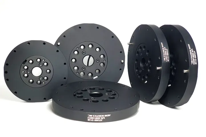
1.2 Key features
•
Ultra-Thin torque sensor
•
All-in-one sensor (No additional amplifier)
•
Digital output communications (CAN, etc)
•
Easy installation and data collection
•
Collaborative robot, industry application, automation.
1.3 Specs.
Index | Unit / Series | ATS50-D100 | ATS100-D100 | ATS200-D100 | ATS400-D128 |
Operating voltage | VDC | 5 | - | - | - |
Max. safe excitation voltage | VDC | 10 | - | - | - |
Nominal torque range (T_N) | Nm | 50 | 75 | 150 | 300 |
Peak torque | Nm | 75 | 100 | 200 | 400 |
Breaking torque (related to T_N) | % | 200 | 200 | 200 | 175 |
Dimensions | mm | D100 x H14 | D100 x H14 | D100 x H14 | D100 x H14 |
Weight | g | 210 | 210 | 215 | 360 |
Temperature | ℃ | 10-50 | - | - | - |
Sample rate | Hz | 1000 | - | - | - |
Interfaces | 1,000Kbps | CAN | - | - | - |
Connector | Ø2.6mm 4pin cable | CAN_H / CAN_L / VCC / GND | - | - | - |
1.4 Flyer
2. Installation Guide
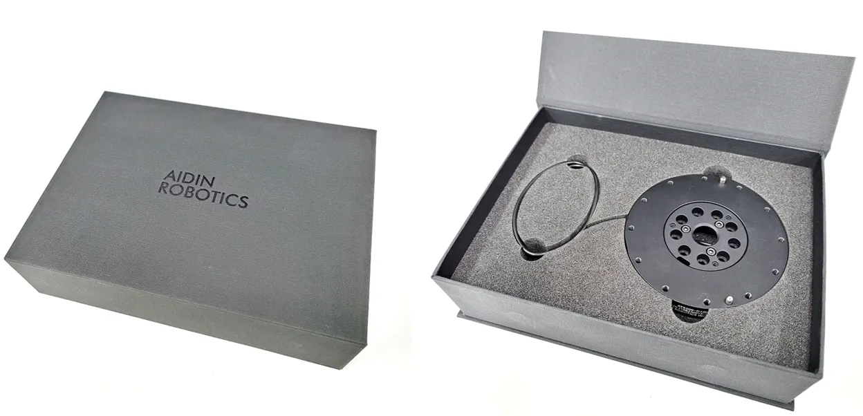
2.1 Components
•
ATS series x 1 EA
•
No separate components other than special order (integrated cable)
2.2 Mounting
•
Required to tighten with appropriate torque for each bolt.
•
When disassembling the sensor's own bolts, performance is not guaranteed and A/S is not possible.
•
Be careful of cable cutting and excessive pulling.
•
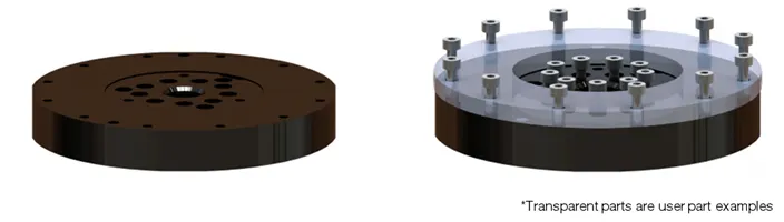
The lower fastening part is a counterbore, and the upper fastening part is composed of a tap.
•
Example of torque sensor connection (the thickness of the part connected to the top is recommended to be at least 10t)
•
Appropriate tightening torque table for each bolt
Bolt | Tightening torque | Torque wrench example |
M3 | 20 kgfcm | 100QL-MH, 50QL-MH |
M4 | 45 kgfcm | 100QL-MH, 50QL-MH |
M5 | 95 kgfcm | 100QL-MH, 225QL-MH |
If the tightening torque is not observed, data may not be output properly.
We recommend tightening with an appropriate torque using a torque wrench.
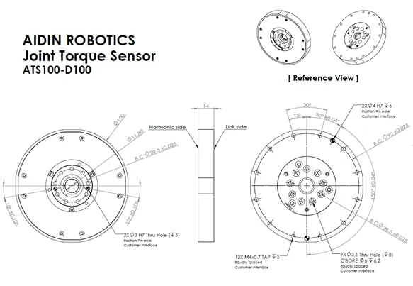
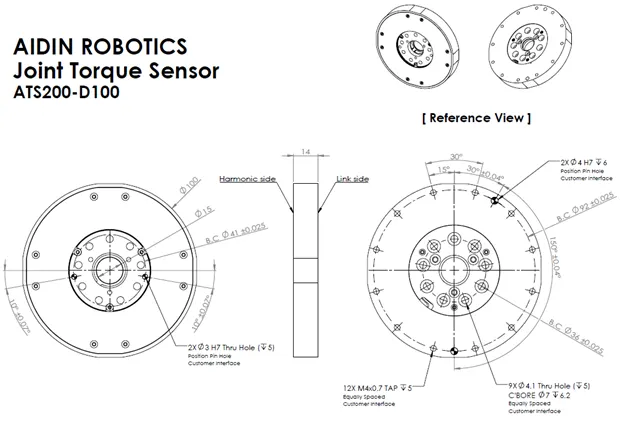
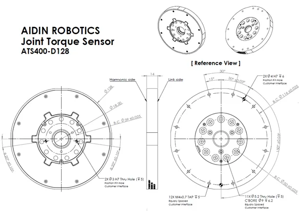
2D drawing
•
ATS100-D100
•
ATS200-D100
•
ATS400-D128
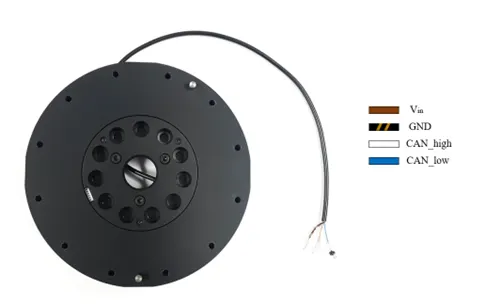
2.3 Wiring
•
Pinout 4pin (CAN_H, CAN_L, V, GND)
•
Apply appropriate operating voltage to Vin (brown) (5-10 V)
•
Connect GND (black) and cable shield (copper wire)
•
120 ohm termination resistance is required between CAN_H (white) and CAN_L (blue)
2.4 Communication
•
CAN protocol
◦
CAN 2.0A
◦
Identifier: Standard Identifier
◦
Bit rate: 1Mbps
◦
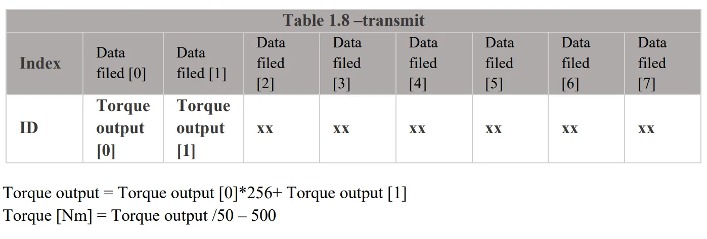
Number of Data: 2 Bytes
◦
sampling rate 1kHz
•
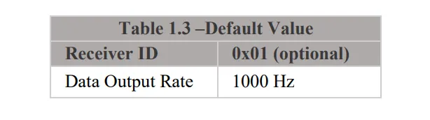
CAN data output
◦
The default ID is 0x01
•
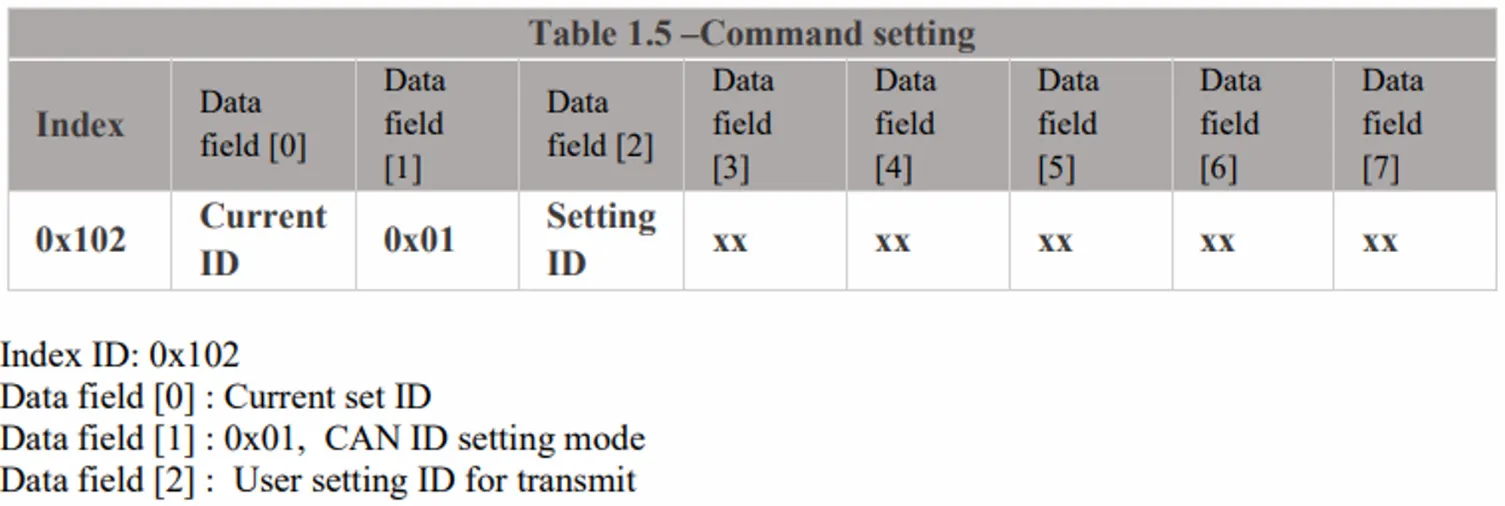
CAN ID Setting mode
◦
ex) Change ID to 0x0A: ID 0x102, Data 01 01 0A (hexadecimal)
2.5 Sample program
•
USB-to-CAN device driver installation
◦
You can use other CAN support boards, but you must use an IXXAT converter to use the provided sample program.
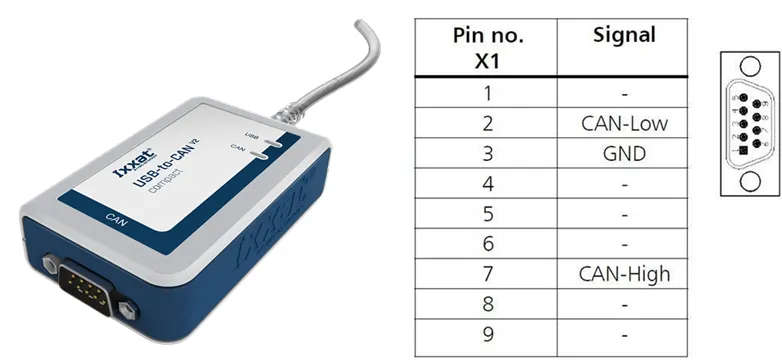
USB-to-CAN V2 (ixxat.com), used version: 1.01.0281.11001
Downloads and Documentation for Ixxat Products, VCI V4 - Windows 11, 10, 8, 7 [Driver, canAnalyser-Mini, Manuals, LabView and other add-ons]*
*Check VCI V4 during installation and reboot PC after installation.
•
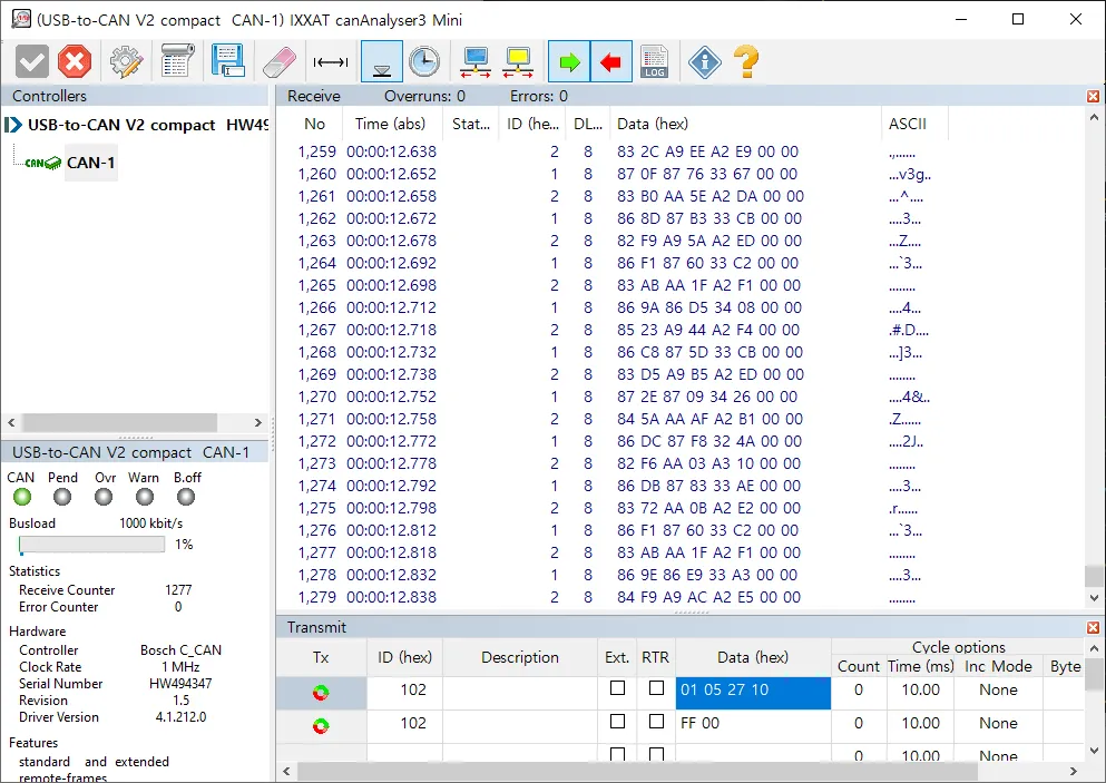
IXXAT CAN monitor
◦
CanAnalyzer3 Mini
windows key→ IXXAT folder → IXXAT CanAnalyzer3 Mini
•
Sample program provided by Aidin Robotics
◦
Install the IXXAT CAN VCI V4 and installer
◦
Sample program
◦
After connecting the sensor, run ATS_sample_program.exe
•
Pop-up screen when running sample program
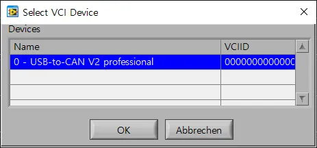
1.
Select VCI Device
Select your device. Devices currently connected to the PC are displayed in a list. Click the applicable device and press the OK button.
※ The sample program was created based on IXXAT’s USB-to-CAN converter.
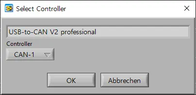
2.
Select Controller
The device name selected in the previous step will be displayed. Select the controller channel below and press the OK button.
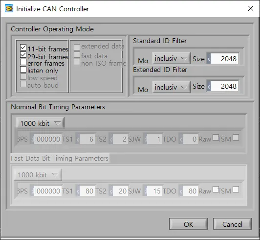
3.
initialize CAN Controller
This is the step to initialize the controller selected in the previous step. Check the frame and baud rate and press the OK button.
•
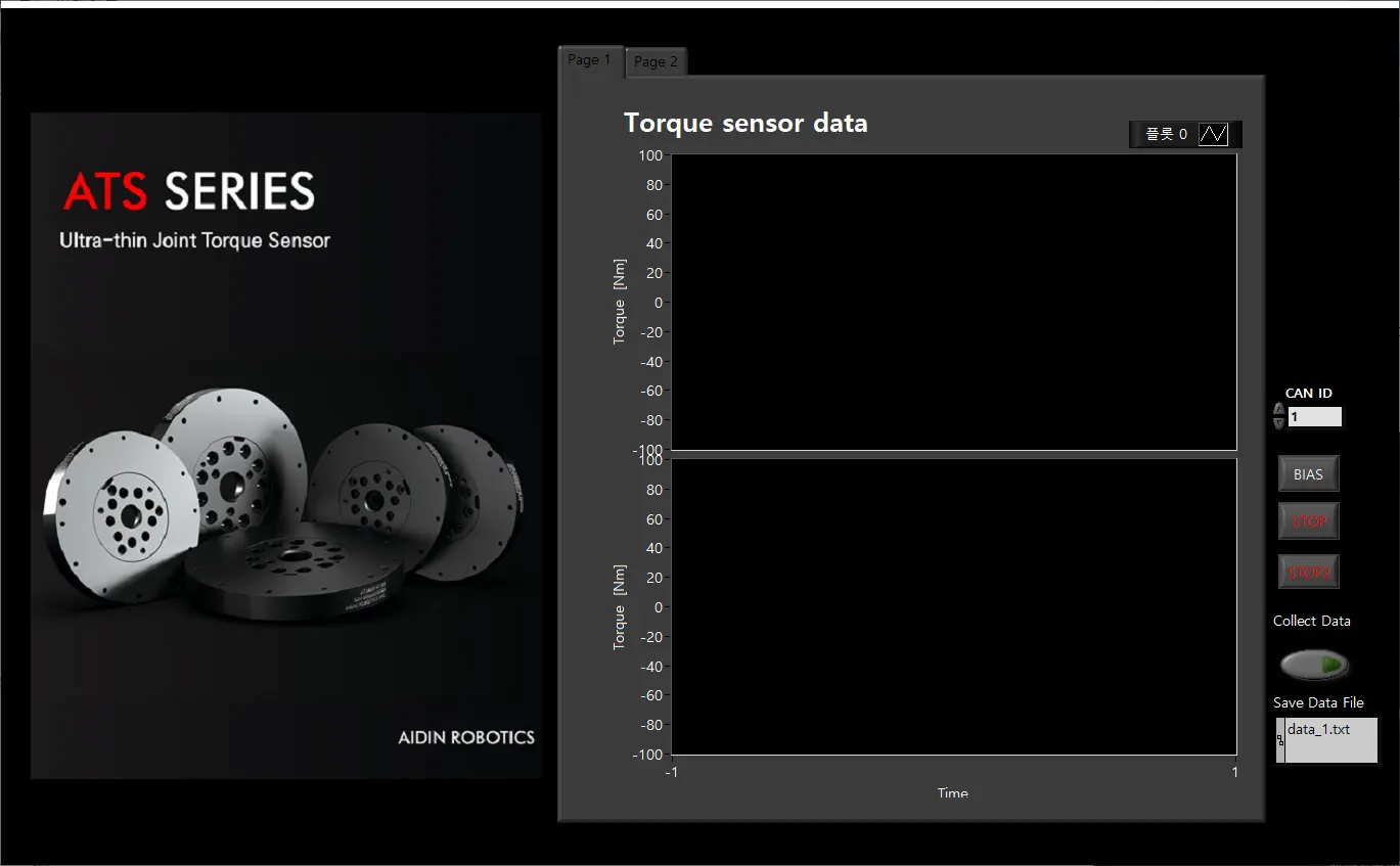
Sample program interface description
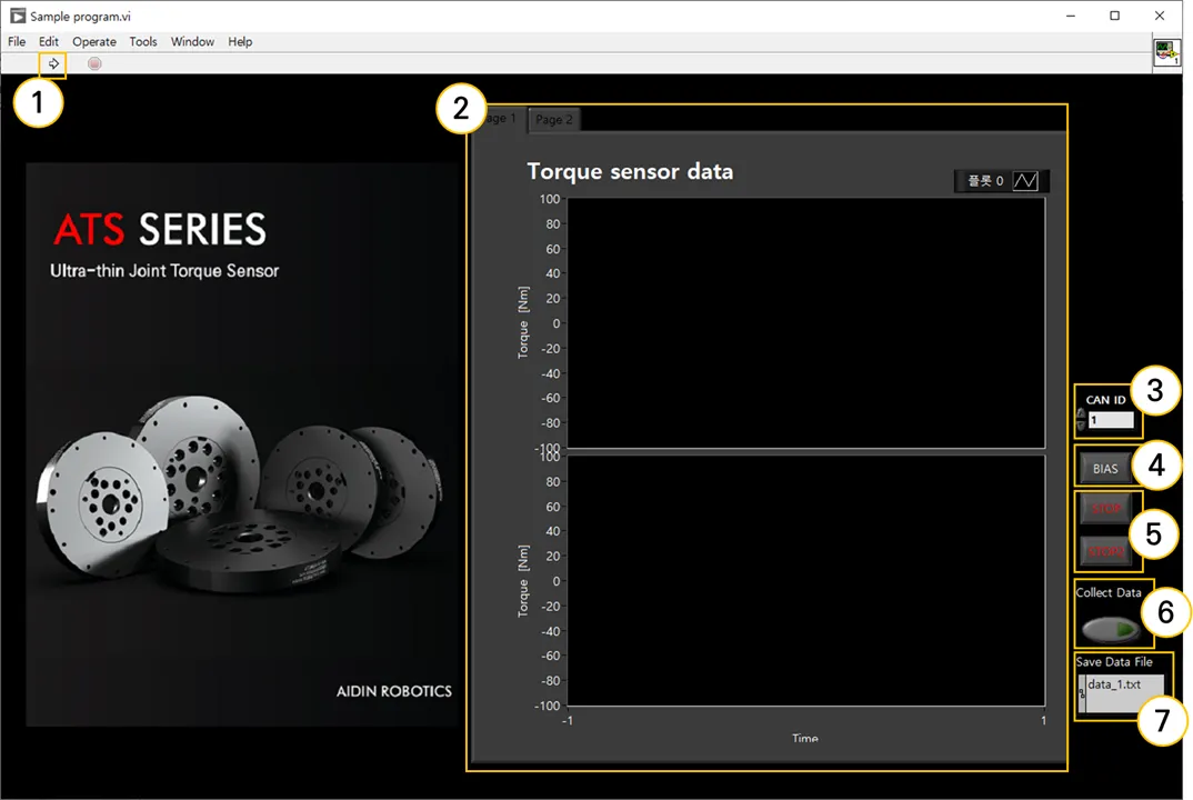
① Program run
Run the sample program. It runs automatically the first time you run it, and after STOP, you can run it by pressing the run button.
② Graph plot
You can check real-time torque (Tz) data in a graph.
③ CAN ID
Set the CAN ID of the connected sensor. If there is more than one ID, enter the lowest ID.
ex) In case of 0x10(16), 0x11(17), enter 16 in decimal.
④BIAS
The value is initialized to 0 based on the current torque value. By eliminating installation and attachment factors, the desired force value can be measured.
⑤STOP
Exit the program. Press both STOP buttons and the program ends 3 seconds later.
⑥ Collect Data
Save the torque data log. Please refer to the explanation regarding data storage on the page below.
⑦ Save Data File Path
Set the path to save the torque data log. Please refer to the explanation regarding data storage on the page below.
•
Save data log
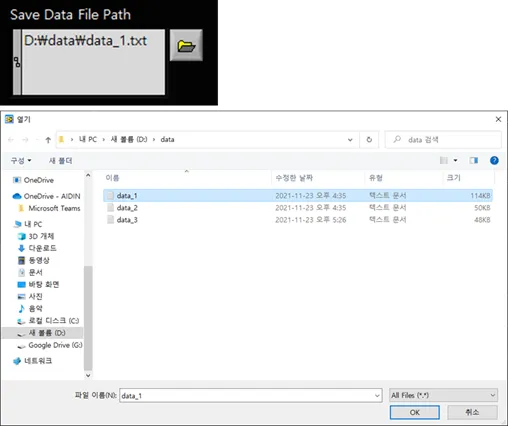
1.
Set storage directory
Click the folder button to open a pop-up window. Select the file (.txt) in the desired directory and press the OK button to specify it. Check the path indicated in Path. (If there is no specified file in the relevant path, a file is automatically created)
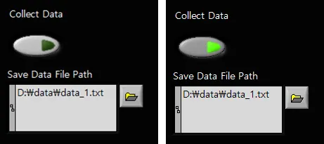
2.
Data log storage
Click the button below Collect Data to start saving. When saving, the button appears in fluorescent color. To end saving, press the same button to end it. Data is stored cumulatively in files, so it is recommended that you specify a new file for each save.
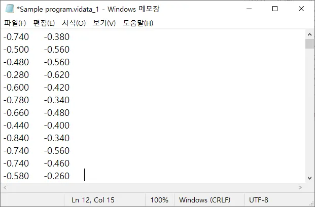
3.
Check data log
You can check the saved torque data by opening the file in the directory. (Unit Nm)