
revision date: 2026.04.29
FOREWORD
Thank you for purchasing our Force Torque sensor. This manual contains the information necessary for the correct use of the AIDIN ROBOTICS AFT100-D20 sensor.
Please carefully read this manual when using this software.
Please note that the basic performance of the product will not be exhibited when the robot system is used out of conditions.
This manual describes possible dangers and consequences using Force Torque sensor. Be sure to comply with safety precautions written in this manual to use safety and correctly.
NOTICE
This manual Do NOT allow copy, reproduction or share without authorization of AIDIN ROBOTICS.
Please notify us any errors in this manual or the provided instructions.
MANUFACTURER
AIDIN ROBOTICS
SAFETY PRECAUTIONS
Installation of Force Torque sensor MUST be performed by qualified personnel in accordance with national and local codes. Please carefully read this manual when using this software.
WARNING & CAUTION
This symbol indicates that a danger of possible serious injury or death exists if the associated instructions are not followed properly.
This symbol indicates that a danger of possible harm to people or physical damage to equipment and facilities exists if the associated instructions are not followed properly.
AFT20-D15, AFT50-D15 sensors from AIDIN ROBOTICS meet CE-certified “A Class”
1. Introduction
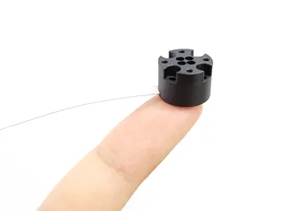
1.1 Miniature 6-axis Force Torque Sensor
1.2 Key features
•
Miniature 6-axis force/torque sensor
•
All-in-one sensor (No additional amplifier)
•
Digital output communications (CAN)
•
Easy installation and data collection
•
Grippers, robot hands, medical, and VR/haptics
1.3 Specs.
Index | Unit | AFT20-D15 | AFT50-D15 |
Operating voltage | VDC | 5 | 5 |
Max. safe excitation voltage | VDC | 10 | 10 |
Force range | N | 20 | 50 |
Torque range | Nm | 0.1 | 0.25 |
Break force | N | 30 | 75 |
Break torque | Nm | 0.15 | 0.35 |
Force resolution | N | 0.05 | 0.1 |
Torque resolution | Nm | 0.0001 | 0.0002 |
Force Noise-free resolution (STD) | N | 0.2 | 0.3 |
Torque Noise-free resolution (STD) | Nm | 0.0005 | 0.001 |
Sample rate | Hz | 100 | 100 |
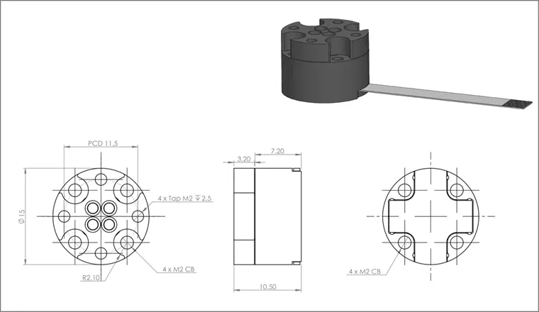
Dimensions | mm | D15 x H10.5 | D15 x H10.5 |
Weight | g | 3.2 | 3.2 |
Temperature | 10-50℃ | 10-50℃ | |
Interfaces | CAN | CAN | |
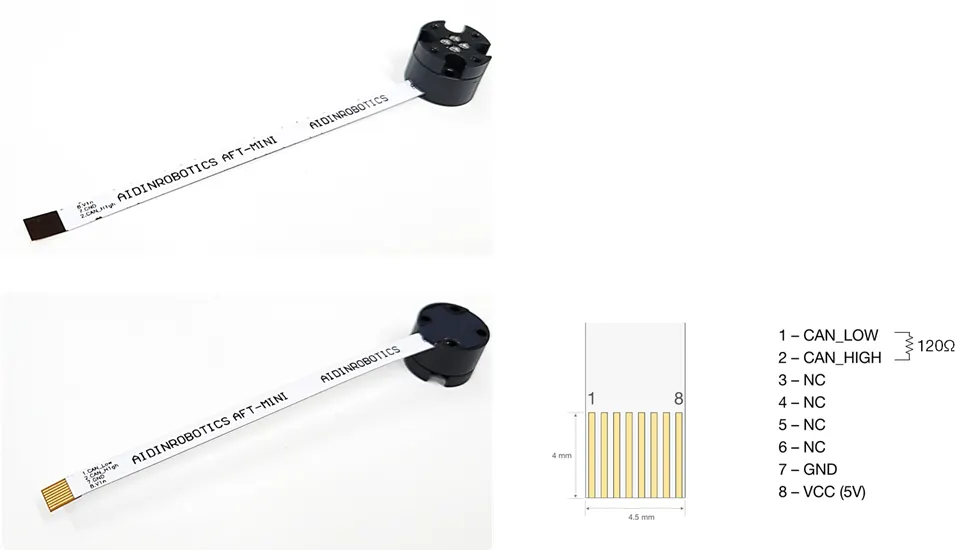
Connector | FPC: 0.5 pitch, 8pin Length: 50, 100, 200 mm For User: CAN_H / CAN_L / VCC / GND | FPC: 0.5 pitch, 8pin Length: 50, 100, 200 mm For User: CAN_H / CAN_L / VCC / GND |
1.4 Flyer
2. Installation Guide
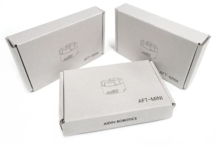
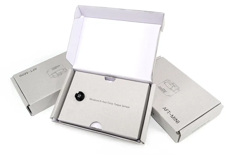
2.1 Components
•
AFT-MINI x 1 EA (FPC cable integrated, selected when ordering)
•
FPC-DIP conversion board (for testing)
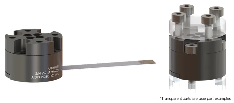
2.2 Mounting
•
Must be fastened with M2 bolt 1kgfcm (0.1Nm)
•
Performance cannot be guaranteed and A/S is not possible when disassembling internal bolts
•
Be careful of cable cuts and excessive pulling
If the tightening torque is not observed, data may not be output properly.
•
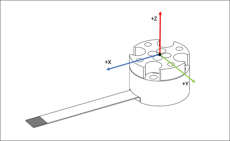
Force torque coordinate system
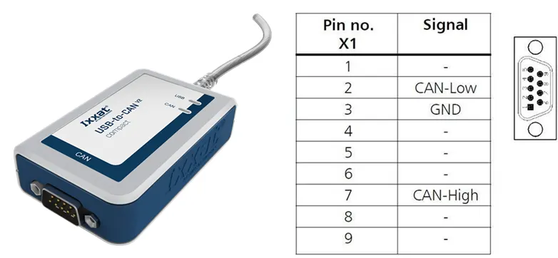
2.3 Connection
•
Cable pinout
◦
For user: CAN_H / CAN_L / VCC / GND (4pin)
◦
60 - 120 Ohm termination resistor should be connected between CAN_H and CAN_L
◦
Length: 50, 100, 200 mm (order option)
•
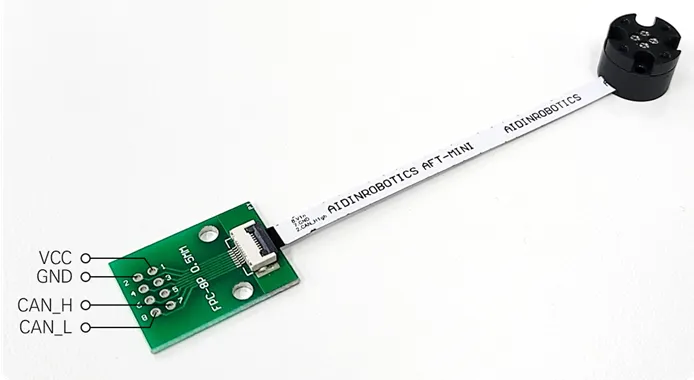
Conversion board connection example
◦
FPC 0.5mm pitch to DIP converting board
◦
For easy test set-up
◦
60-120 Ohm termination resistance required (between CAN_H and CAN_L)
◦
For system integration, it is recommended to have a connector built into the board.
(Connector information: FFC/FPC connector 8P ZIF, R/A, SMT ONE TOUCH FLIP LOCK)
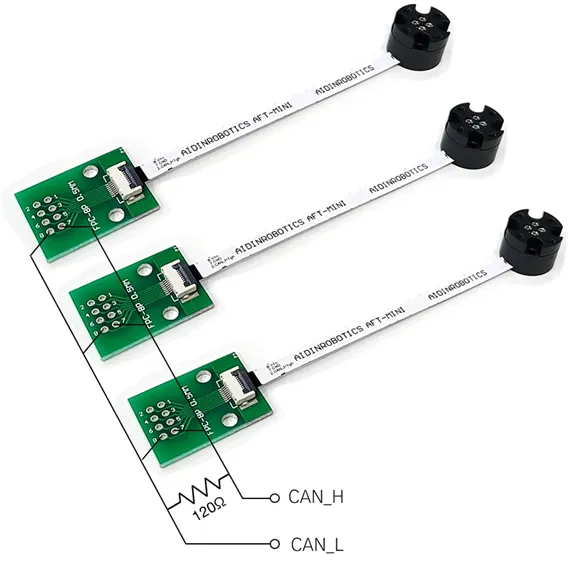
•
Example of CAN_H, CAN_L line and terminating resistance configuration for multiple connections
(individual ID setting required- factory setting)
•
Output data format
◦
The default CAN IDs are 0x1A and 0x1B (decimal 26 and 27), and are assigned prior to shipment.
◦
If custom CAN ID assignment is required, please specify your request at the time of order.

3. Software
•
USB-to-CAN device driver installation
◦
You can use other CAN support boards, but use IXXAT's converter to use the provided sample program.
USB-to-CAN V2 (ixxat.com), version used in the manual: 1.01.0281.11001
IXXAT CAN VCI V4 - Windows drivers, VCI V4 - Windows 11, 10, 8, 7 [Driver, canAnalyser-Mini, Manuals, LabView and other add-ons]*
*When installing, check VCI V4 and reboot the PC after installation (required)
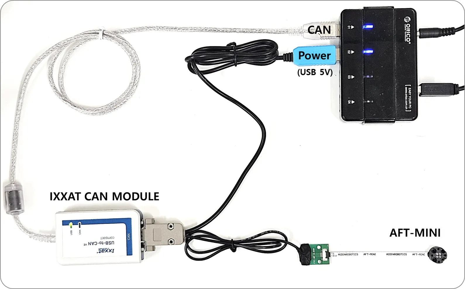
•
Test cable connection setup
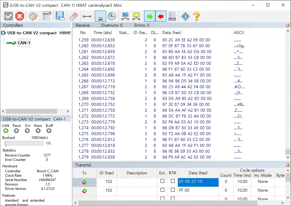
•
CAN bus program (provided by IXXAT)
◦
CanAnalyzer3 Mini
windows→ IXXAT→ IXXAT CanAnalyzer3 Mini
•
Sample program provided by Aidin Robotics
◦
Install CAN driver and reboot(required) - Skip if already completed above
IXXAT CAN VCI V4 - Windows drivers
◦
Install sample_installer (run sample_install.exe)
◦
After connecting the sensor, run AFT-MINI SAMPLE.exe
•
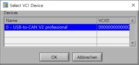
Pop-up screen
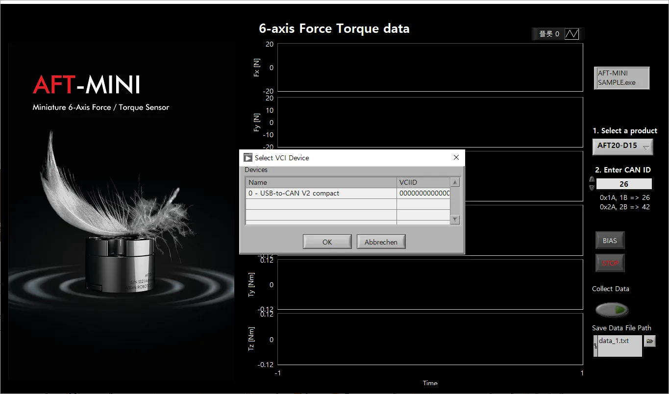
1.
CAN device selection
Select your device. Devices currently connected to the PC are displayed in a list.
Click the applicable device and press the OK button.
※ The sample program was created based on IXXAT's USB-to-CAN converter.
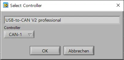
2.
CAN Controller Selection
The device name selected in the previous step will be displayed. Select the controller channel below and press the OK button.
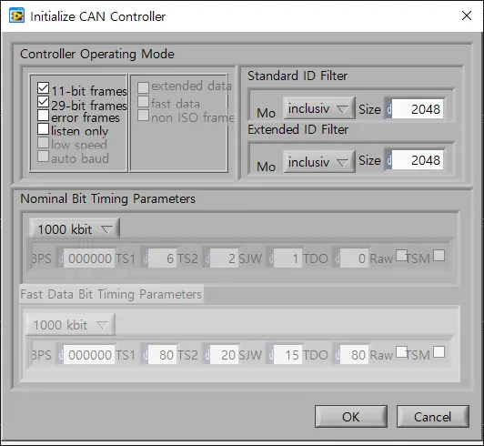
3.
CAN controller initial setup
This is the step to initialize the controller. Check the baudrate and press the OK button.
4.
Select product and enter CAN ID
Choose the product you are using between AFT20-D15 and AFT50-D15.
Enter the CAN ID of the sensor you connected.
(Default 1A, 1B ⇒ Decimal 26 input, can be checked in IXXAT CanAnalyzer)
•
Interface description
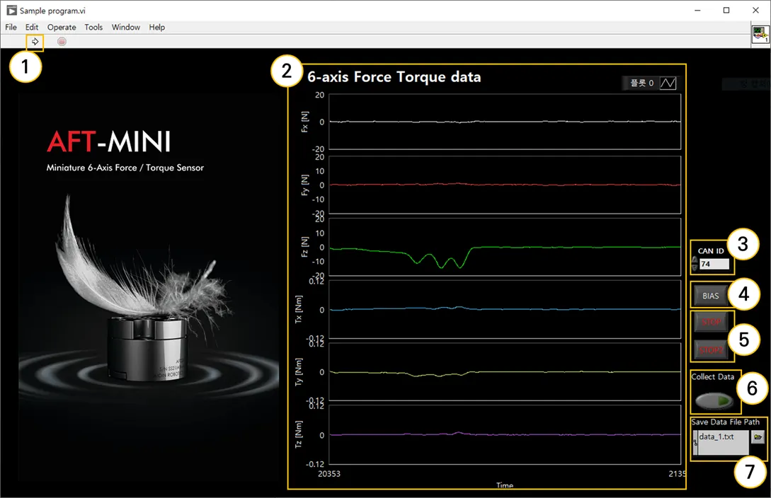
① Program run
Run the sample program.
② Graph plot
You can check real-time data of 6-axis force/torque data (Fx, Fy, Fz, Tx, Ty, Tz) in graphs.
③ CAN ID
Set the CAN ID of the connected sensor. If there is more than one ID, enter the lowest ID.
ex) In case of 0x1A(26), 0x1B(27), input 26
④ BIAS
Initialize all 6-axis force/torque data to zero. By eliminating installation and attachment factors, the desired force value can be measured.
⑤ STOP
Exit the program. Press both STOP buttons and the program ends in 3 seconds.
⑥ Collect Data
Saves force/torque data logs. Please refer to the explanation regarding data storage on the page below.
⑦ Save Data File Path
Set the file name to save force/torque data logs. Please refer to the explanation regarding data storage on the page below.
3.1 Save data log
1.
Save directory settings
Set the name of the file to save the data. The file will be saved in the folder where the executable program is located, and if there is no file with that name, it will be automatically created. Since the data is accumulated in the file, we recommend that you save it by specifying a new file each time you save it.
2.
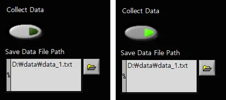
Collect data
Click the button below Collect Data to start saving. The button lights up when saving.
To end saving, press the button again. Data is stored cumulatively in files, so it is recommended that you specify a new file for each save.
3.
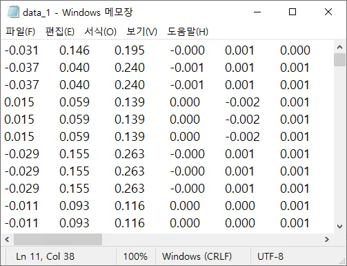
Check data log
You can check the saved force/torque data by opening the files in that directory. Data is stored in each column in the following order: Fx, Fy, Fz, Tx, Ty, and Tz.
FAQ
전체
Search