revision date: 2026.04.28
FOREWORD
Thank you for purchasing our Force Torque sensor. This manual contains the information necessary for the correct use of the AIDIN ROBOTICS AFT200-D80 sensor.
Please carefully read this manual when using this software.
Please note that the basic performance of the product will not be exhibited when the robot system is used out of conditions.
This manual describes possible dangers and consequences using Force Torque sensor. Be sure to comply with safety precautions written in this manual to use safety and correctly.
NOTICE
This manual Do NOT allow copy, reproduction or share without authorization of AIDIN ROBOTICS.
Please notify us any errors in this manual or the provided instructions.
MANUFACTURER
AIDIN ROBOTICS
SAFETY PRECAUTIONS
Installation of Force Torque sensor MUST be performed by qualified personnel in accordance with national and local codes. Please carefully read this manual when using this software.
WARNING & CAUTION
This symbol indicates that a danger of possible serious injury or death exists if the associated instructions are not followed properly.
This symbol indicates that a danger of possible harm to people or physical damage to equipment and facilities exists if the associated instructions are not followed properly.
AFT200-D80-EN sensor from AIDIN ROBOTICS meets CE-certified “A Class”
1. Introduction
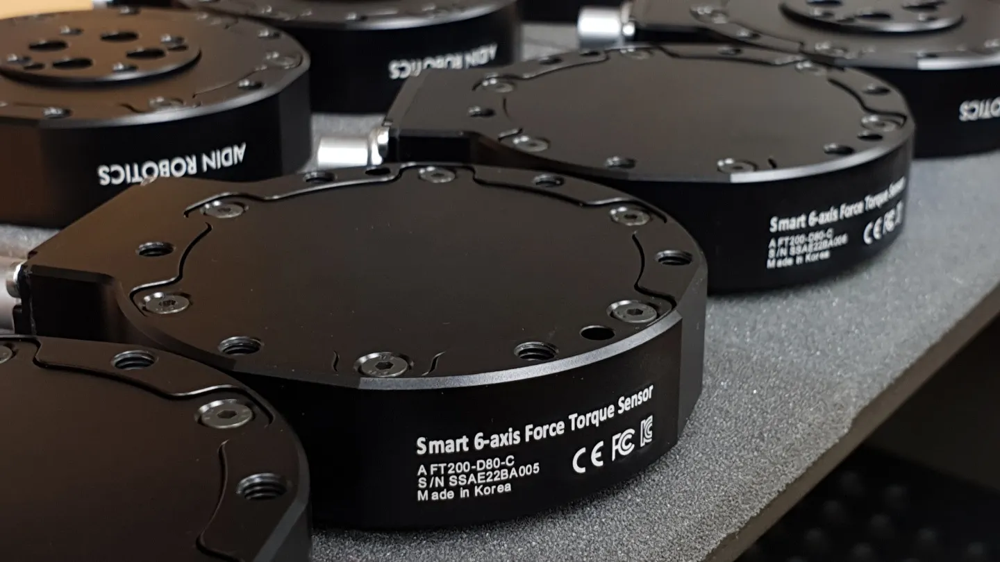
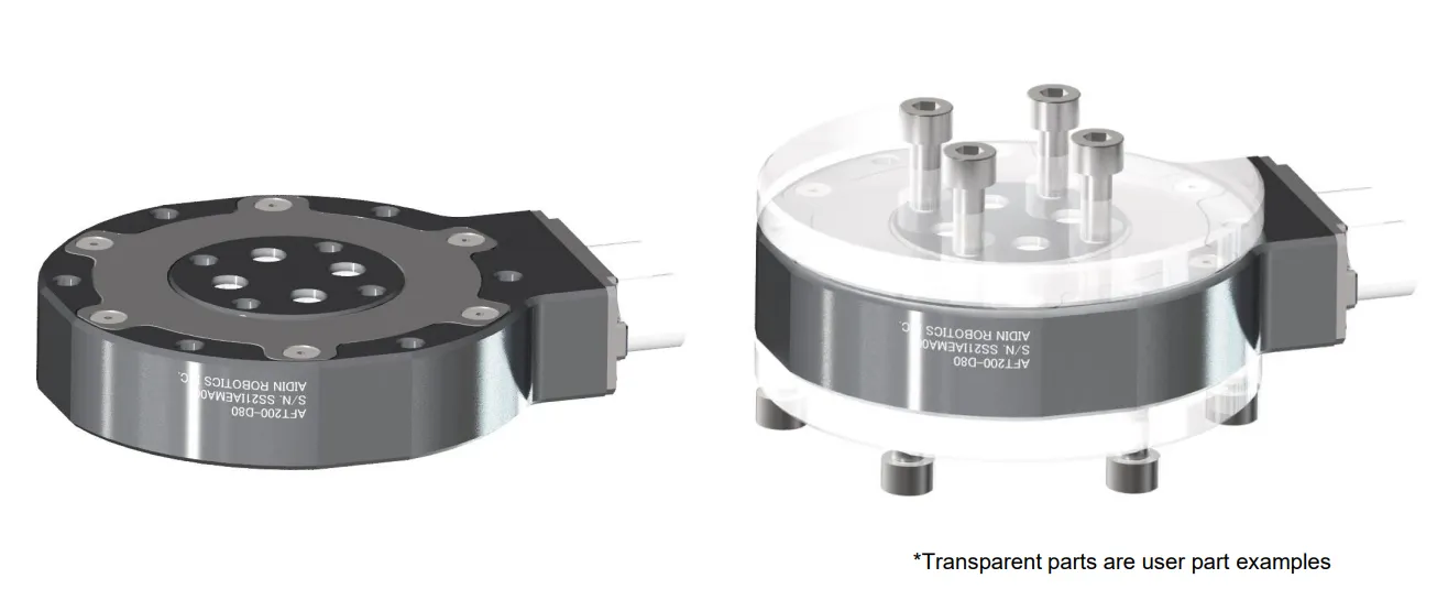
1.1 Smart 6-axis Force Torque Sensor, AFT200-D80
1.2 Key features
•
Smart 6-axis force/torque sensor
•
All-in-one sensor (No additional amplifier)
•
Digital output communications (EtherNET)
•
Easy installation and data collection
•
Grippers, robot hands, collaborative robot, industrial robot
1.3 Specs.
Index | Unit | Value |
Operating voltage | VDC | 12 |
Max. safe excitation voltage | VDC | 24 |
Nominal force range | N | 200 |
Nominal torque range | Nm | 15 |
Limit force (Fxyz) | N | 300 |
Limit torque | Nm | 22.5 |
Force Resolution | N | 0.15 |
Torque Resolution | Nm | 0.015 |
Force Noise-free resolution (STD) | N | 0.4 |
Torque Noise-free resolution (STD) | Nm | 0.025 |
Maximum sample rate | Hz | 1,000 |
Dimensions | mm | D80 x H21.5 |
IP rating | IP65 | |
Operating temperature | 10-50℃ |
1.4 Flyer
2. Installation Guide
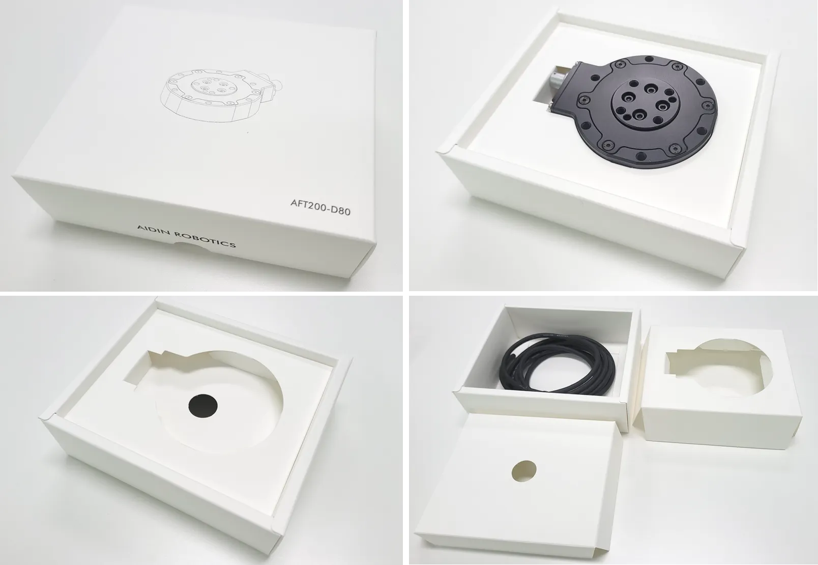
2.1 Basic Components
•
AFT200-D80 x 1 EA
•
1.5 m Cable x 1 EA
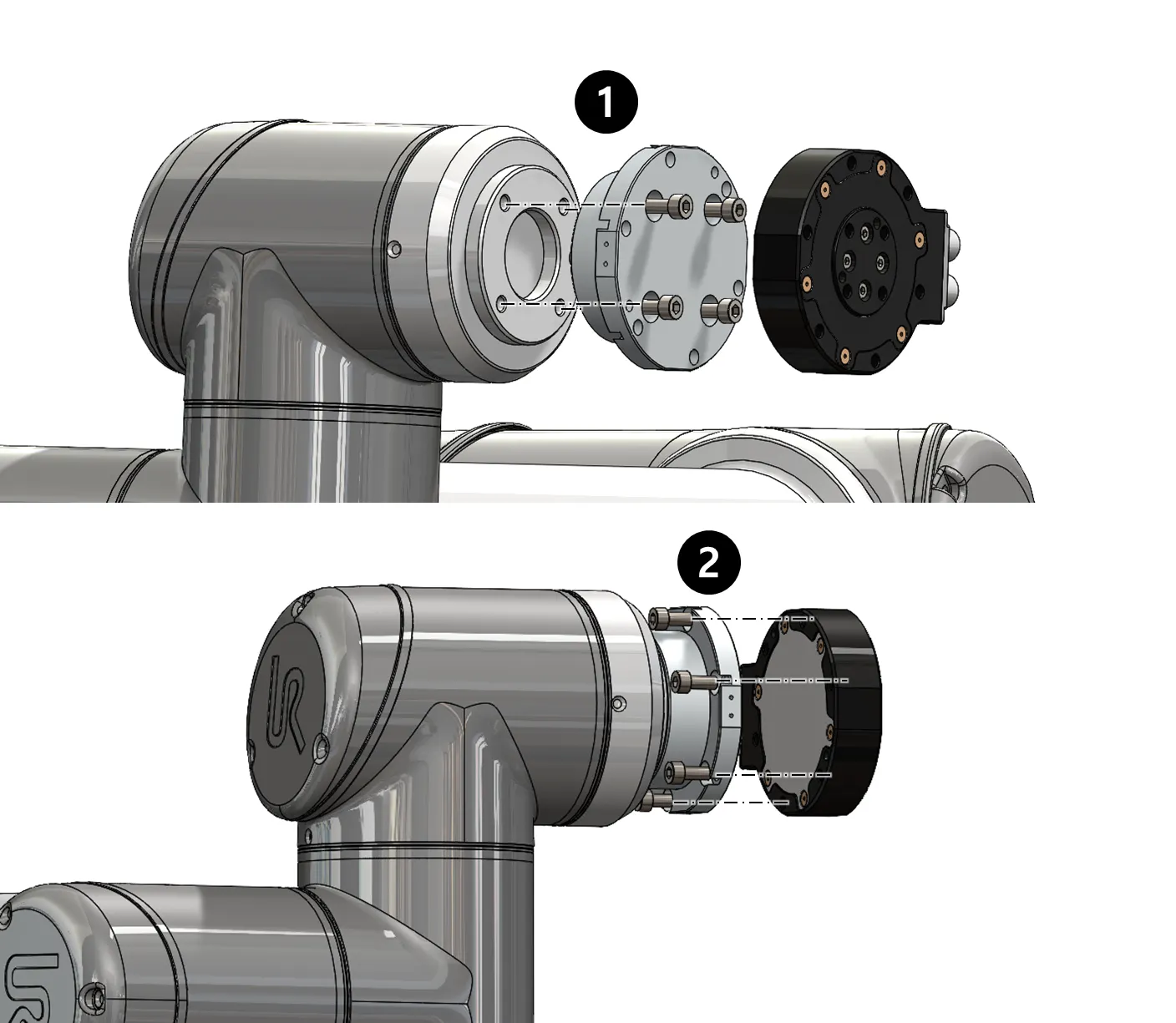
2.2 Mounting
•
M5 bolt 5.2Nm required for tightening
•
Performance cannot be guaranteed and A/S not possible when disassembling internal/external bolts
•
Sensor tightening order
•
CAUTION OF CABLE CUTTING AND EXCESS PULLING
•
Secure the sensor line with the robot so that it does not pull as it moves
◦
Do not fix it to the robot using cable ties, etc., or use cable ties to fix it in a bundle shape like other wires
◦
We recommend that you use Velcro to fix it with the robot, and please use Velcro to fix it when fixing it in a bundle form with other lines
Performance CANNOT be guaranteed if not followed to the tightening torque guide.
If the sensor line is not fixed to the robot, the output signal may have a noise due to the pulled by robot
Please check More detail setup guide as follow:
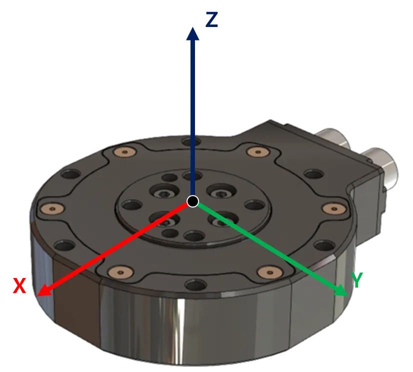
2.3 AXIS & Drawings
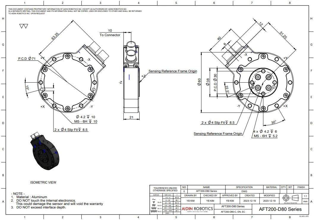
Drawing File :
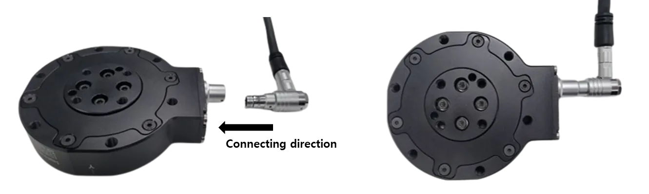
Port Location Notice
•
EtherCAT Type model has two ports: IN and OUT.
•
Ethernet Type model has one port, located on the left side.
•
CAN Type model has one port, located on the right side.
STEP File:
2.3 Wiring
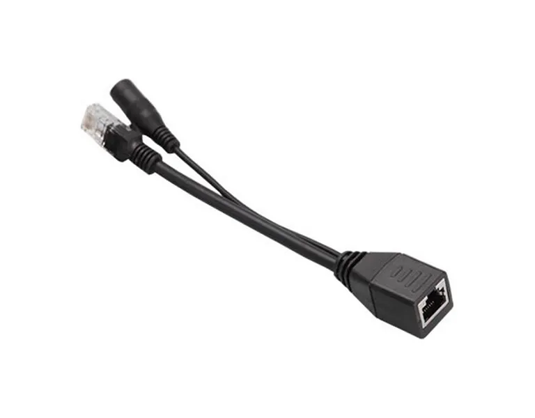
The EtherNET device are provided with a POE injector and a 12-24V AC/DC power supply. The sensor is complying with 802.3af Mode A protocol, but the power is being delivered by only one unused pair of the Cat5e ethernet cable. Make sure DO NOT apply the over voltage to the sensor cable. The user should connect the sensor cable to the “POE” marked port of the injector.
Other POE Injectors compatible with the 802.3af Mode A can be used with 12-24V supply voltage.
2.3.1 Pin out
•
Use POE Connector to connect Power & EtherNET signal
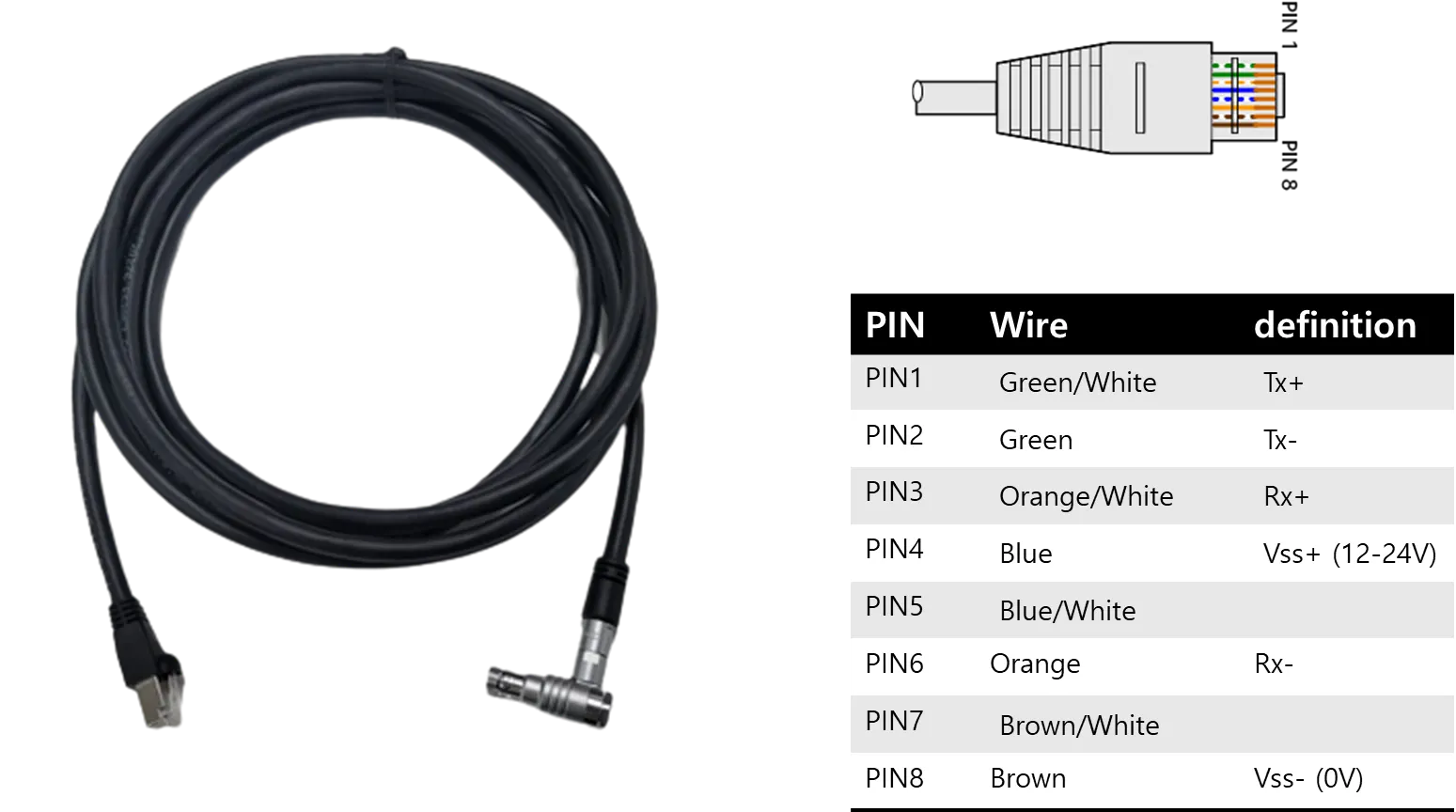
Cable wires color | EtherCAT Signal | |
1 | Green/White | TX+ |
2 | Green | TX- |
3 | Orange/White | RX+ |
4 | Blue | 12V |
5 | Blue/White | NC |
6 | Orange | RX- |
7 | Brown/White | NC |
8 | Brown | GND |
2.5 EtherNET interface
The AFT200-D80-EN model support the RUN state where the sensor is providing the force/torque measurements. Also the IMU measurements can be activated by using activating signal to AFT200-D80-EN sensor. To activate the IMU signal or biasing the sensor signal, please follow the instructor in section 2.6.
The EtherNET interface is used to give the users the following capabilities:
• Read the Product Number, Serial Number, etc.
• Read Force/Torque Data
• Read IMU data
2.5.1. Digital Output
Name Type | Size | Bit Size |
Force x | REAL | 32 |
Force y | REAL | 32 |
Force z | REAL | 32 |
Torque x | REAL | 32 |
Torque y | REAL | 32 |
Torque z | REAL | 32 |
Acceleration x | REAL | 32 |
Acceleration y | REAL | 32 |
Acceleration z | REAL | 32 |
Angular Rate x | REAL | 32 |
Angular Rate y | REAL | 32 |
Angular Rate z | REAL | 32 |
Temperature | REAL | 32 |
2.5.2. Output type
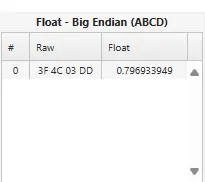
•
The sensor output is in big-endian format. Please convert the final value to float using big-endian before use.
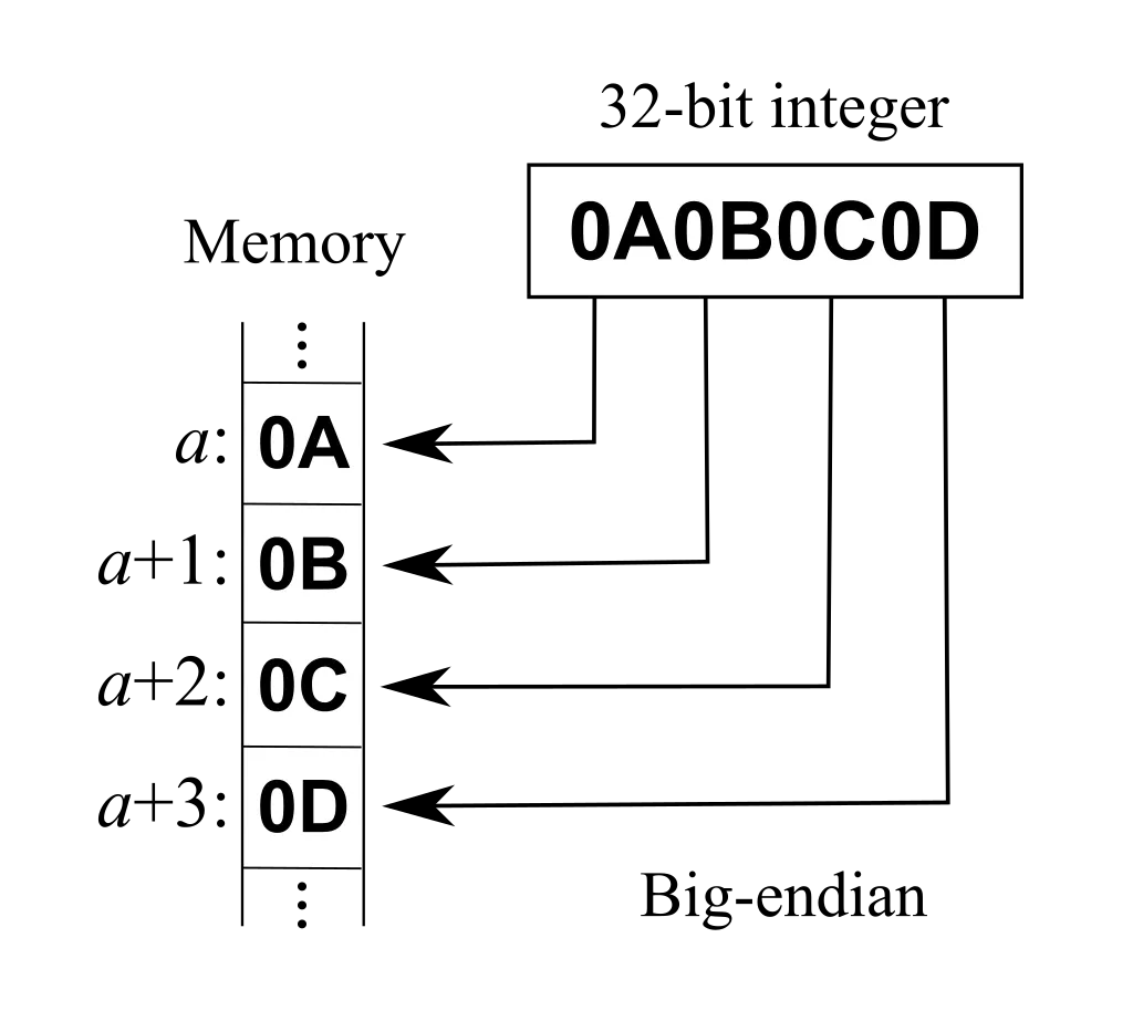
ex) Fx = ‘3F4C03DD’
To stabilize the sensor signal, it is recommended to have a running time of about 30 minutes.
* Please leave the sensor data on for at least 10 minutes before using it
The first 10 minutes of sensor output data can cause data to flow.
2.6 Force/Torque Out of Range
The sensor can operate up to its nominal capac ity, while a single axis load. On Nominal capacity reading is incorrect and invalid.
The nominal capacity of composite loading is The following diagram illustrates a complex loading scenario. The sensor cannot operate outside the normal operating area
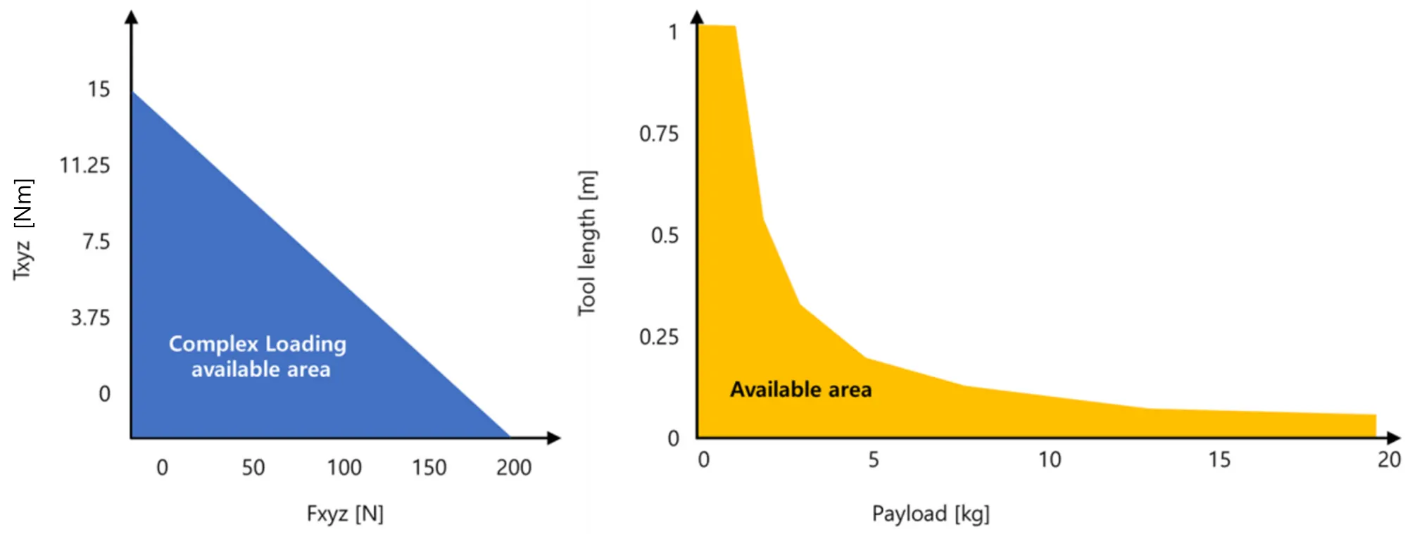
The following graph shows the range of payloads and tool lengths that can be used with AFT200-D80-EN sensor for applications requiring high or moderate precision.
• The total percentage of the calibrated range used by Fxy and Tz axes is greater than 105%. Refer to the following Fxy, Tz equation.
• The total percentage of the calibrated range used by Fz and Txy axes is greater than 105%. Refer to the following Fz, Txy equation.
3. WebServer
3.1 . Connecting Through Ethernet
Different methods for setting an IP address and how to configure a Windows 10 operating
system to connect the sensor to the AFT200-D80-EN webserver.
To connect through Ethernet, the user must configure the IP address setting of the AFT200-D80-EN sensor. The sensor can connect through Ethernet by one of the following options:
10 operating
system to connect the sensor to the AFT200-D80-EN webserver.
To connect through Ethernet, the user must configure the IP address setting of the AFT200-D80-EN sensor. The sensor can connect through Ethernet by one of the following options:
1. Connect the Ethernet cable into a port of an Ethernet switch.
2. Connect the Ethernet cable directly to a computer’s Ethernet interface.
3.2 IP Address Configuration for Ethernet
Configure an IP address for the AFT200-D80-EN sensor with one of the following methods:
Method 1: Set the IP address to a static value stored on the Communication Settings web
page.
Method 2: The DHCP server assigns an IP address.
The initial setting of AFT200-D80-EN sensor is set as static IP address set to 192.168.1.199.
(*If the initial IP address is not working, please try again with this IP address: 192.168.1.182. or 192.168.1.100.)
If the user wants to change the IP address to DHCP or other Static IP, please enter the Webserver of AFT200-D80-EN (Initial address: 192.168.1.199.) than change the IP address refer to Section 3.3.
3.3 Connecting To the AFT200-D80-EN Webserver Using a Windows Computer
To initially access theAFT200-D80-EN webserver, configure the sensor to work on the network by
assigning an IP address and provide basic information about the network.
For the initial connection, directly connect the computer to the sensor and disconnect from LAN. The senor’s default IP address is 192.168.1.199.
Temporarily change the computer’s Ethernet adapter to a static IP address with the same first three fields as the sensor, for example: 192.168.1.220.
1.
Disconnect the Ethernet cable from the LAN port on the computer.
2.
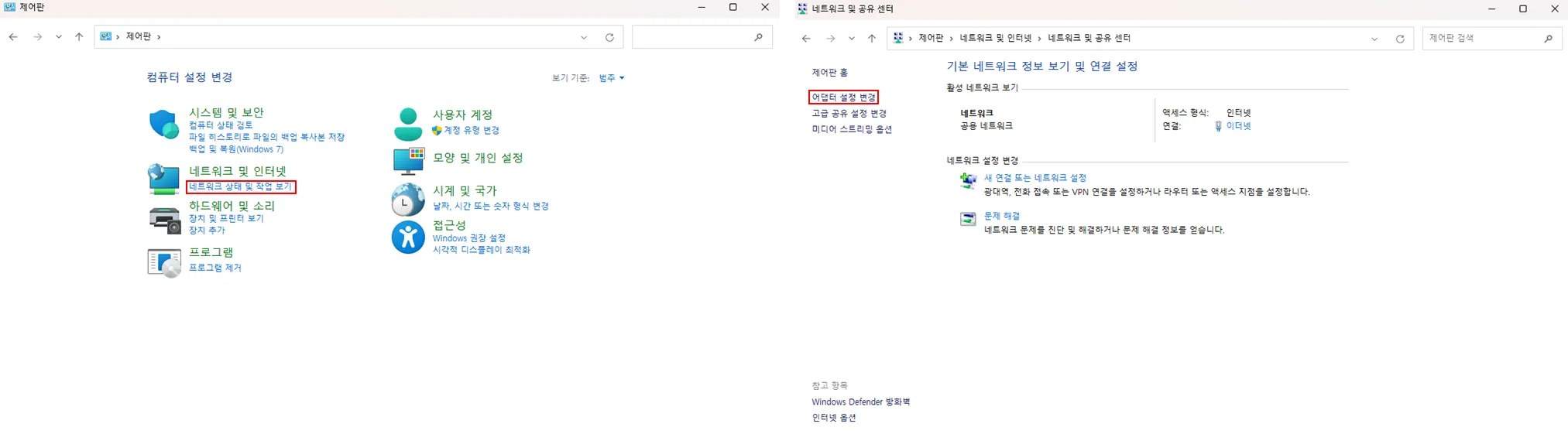
Open the computer’s Internet Protocol (TCP IP) Properties window:
a.
From the Start menu, select the Control Panel.
b.
Click on the Network and Internet icon.
c.
Click on the Network and Sharing Center icon.
d.
Click on the View network status and tasks link.
e.
Click on the Local Area Connection link.
f.
Click on the Properties button.
g.
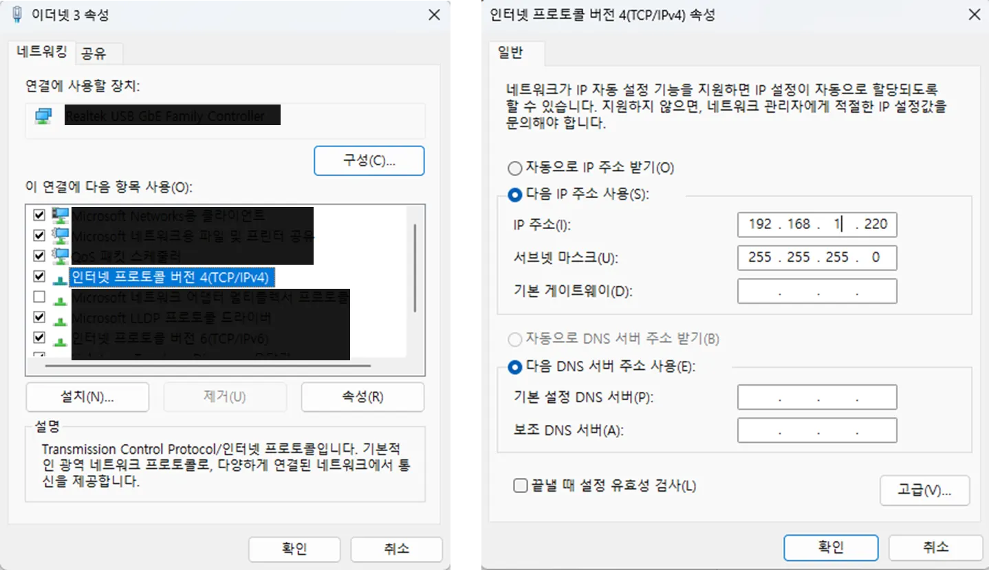
On the Networking tab, and select Internet Protocol Version 4 (TCP/IPv4)
h.
Click on the Properties button
3.
Select the Use the following IP address radio button.
4.
In the IP address: field, type 192.168.1.220 (Temporarily).
5.
In the Subnet mask field, type 255.255.255.0.
6.
Click on the OK button.
7.
On the Local Area Connection Properties window, click the Close button.
8.
Type the address 192.168.1.199 in the browser. The AFT200-D80-EN sensor’s Welcome page appears. (*If the initial IP address is not working, please try again with this IP address: 192.168.1.182. or 192.168.1.100.)
9.
On the left side of the page, there is a menu bar that link to change the valuables of AFT200-D80-EN sensor. Click on the “System Setting” button.
10.
Select an IP address mode:
•
For a static IP address, enter the appropriate values for the IP address, subnet mask, and default gateway. Click the “SAVE SETTING”
•
For DHCP, click the Enabled Combo Box to DHCP, and then click the “SAVE SETTING” button at the bottom of the page. If the Setting is successfully saved, “Set IP to DHCP successfully. Auto reboot device.” message will be shown below.
11.
Open up a new web browser window. Type the sensor’s IP address into the browser’s address bar, and press Enter.
4. Configuring the Sensor with the AFT200-D80-EN Webserver
The AFT200-D80-EN Sensor web server provides full configuration options for the sensor. The menu bar on the left side of the website has a button that leads to the settings page.
Web servers use simple HTML browser scripting and do not require plug-in technology. Non-critical user interface features are unavailable when browser scripting is disabled.
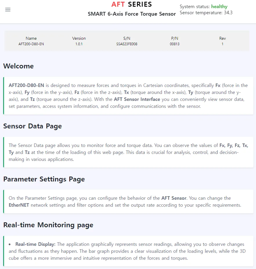
4.1 Welcome Page
When the user enters the sensor’s IP address into the browser address field, the Ethernet F/T Welcome page appears. The Welcome page gives an overview of the AFT200-D80-EN main functions. The bottom of the page lists the calibration used by this configuration.
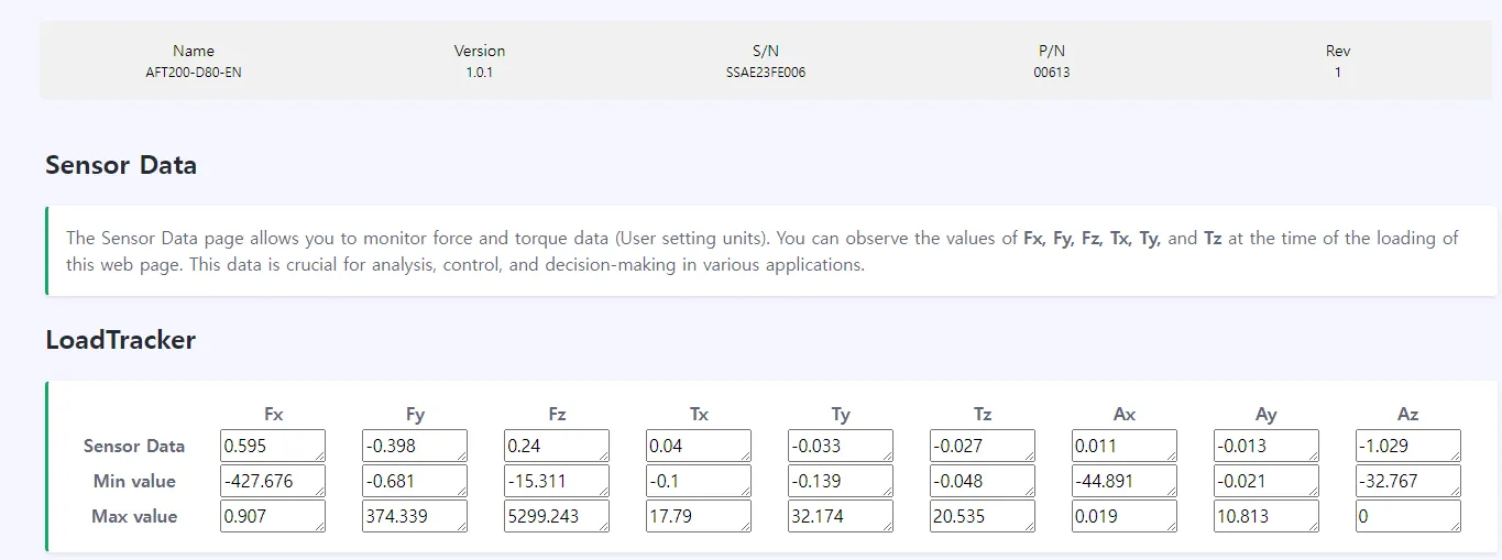
4.2 Sensor Data Page
This page displays the current sensor loading conditions. The information on the Sensor Data page is static and becomes current after a user loads or reloads the page.
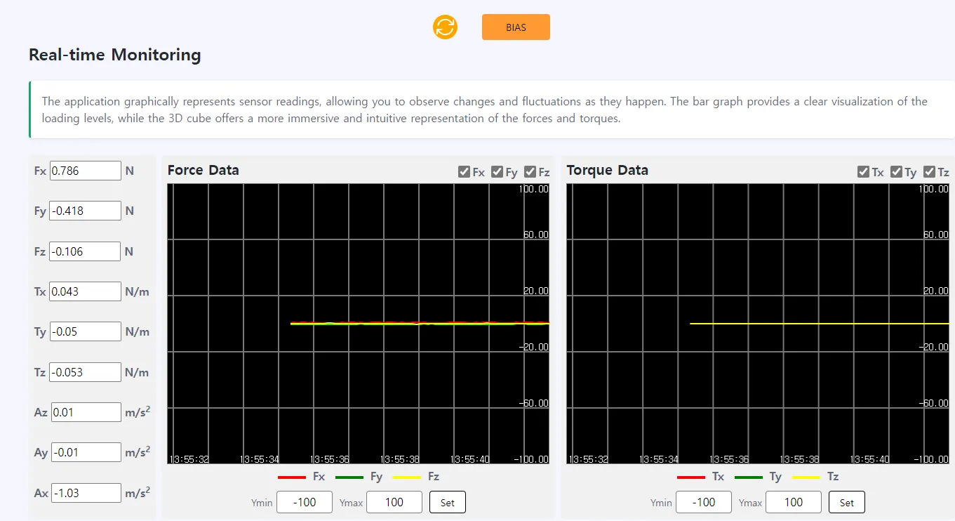
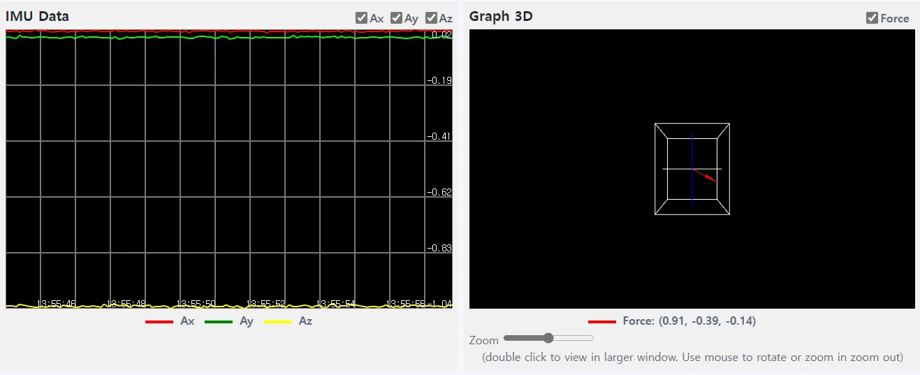
6.6 Real-time Monitoring Page
This page shows real-time F/T data from the AFT200-D80-EN sensor. FT and Acceleration values, and Force/Torque data are shown on the left. Acceleration values and force vector directions are shown below
The force/torque range of the graph can be changed by entering maximum and minimum values at the bottom of the graph
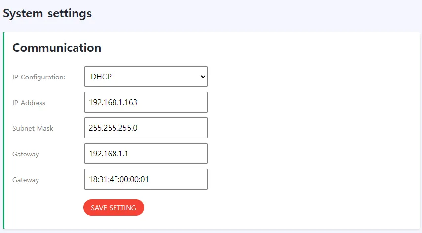
6.7 System settings Page
On the System setting page, users can view and edit Ethernet networking options on the system.
Typically, these settings are set once when the user first sets up the system and do not need to be changed later. Here is a detailed overview of how to set up Ethernet communications with sensors

The fields in Figure of the System setting page are described as follows:
Ethernet network settings:
IP Configuration: Users can set either DHCP or Static IP addresses.
IP Address : The user can set the sensor's IP address
Subnet Mask: This field is for the subnet mask portion of the IP address. ( default 255.255.255.0.) Users should contact their IT department to determine what static conditions they are in the IP subnet mask to be assigned.
Gateway: You know the default gateway to assign.
5. Operation Commands
To stabilize the sensor signal, it is recommended to have a running time of about 30 minutes.
* Please leave the sensor data on for at least 10 minutes before using it
The first 10 minutes of sensor output data can cause data to flow.
1.
UDP Communications
a.
Transmitting mode
i.
Transmit data “00 03 02” in HEX form to the sensor

ii.
The upper Address “192.168.1.199” is PC IP address (Please use the last address “199” by arbitrarily changing it to the address set on your PC)
iii.
Please the transmit Port as “8890”
iv.
The received data is 52 bytes in total, and the values of "Fx, Fy, Fz, Tx, Ty, Tz, Ax, Ay, Az, Gx, Gy, Gz, Temp" are outputted in 4 bytes each in the order in which they are received.
v.
and the output 4-byte data must be interpreted and used in a big-endian
b.
Stop mode
i.
Transmit data “00 03 03” in HEX form to the sensor

c.
Bias mode
i.
Transmit data “00 03 04” in HEX form to the sensor

2.
TCP/IP Communications
a.
Transmitting mode
i.
Transmit data “00 03 02 ” in HEX form to the sensor

ii.
The upper Address “192.168.1.199” is PC IP address (Please use the last address “199” by arbitrarily changing it to the address set on your PC)
iii.
Please the transmit Port as “80”
iv.
The received data is 52 bytes in total, and the values of "Fx, Fy, Fz, Tx, Ty, Tz, Ax, Ay, Az, Gx, Gy, Gz, Temp" are outputted in 4 bytes each in the order in which they are received.
v.
and the output 4-byte data must be interpreted and used in a big-endian
b.
Stop mode
i.
Transmit data “00 03 03” in HEX form to the sensor

c.
Bias mode
i.
Transmit data “00 03 04” in HEX form to the sensor

6. Revisions 25.1
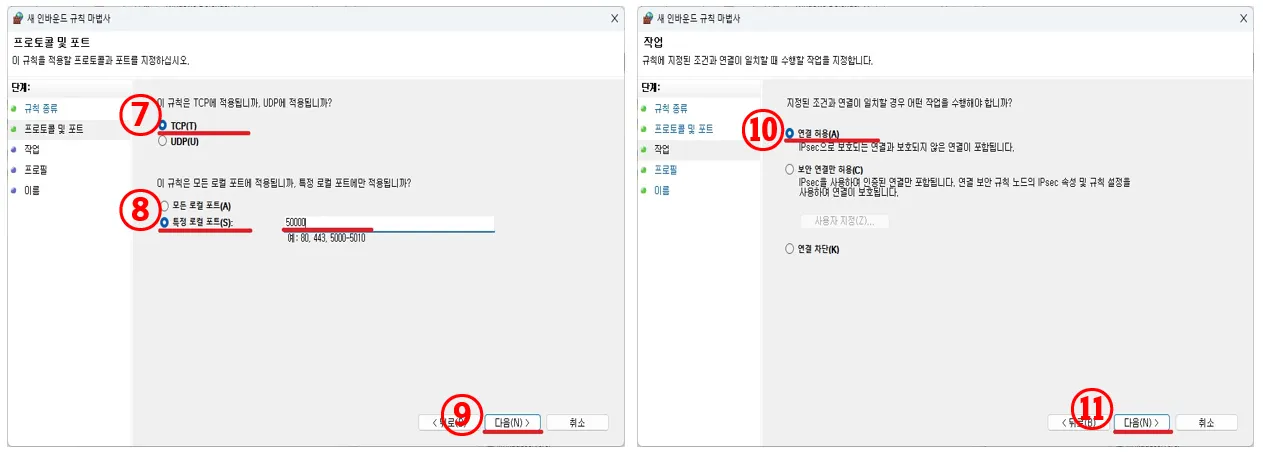
Sensors produced after September 9, 2025,(S/N: SSAG25RI105~),will have the following changes applied:
The sensor-side TCP port has been changed from 80 to 50000.
The sensor-side UDP port has been changed from 8890 to 50000.
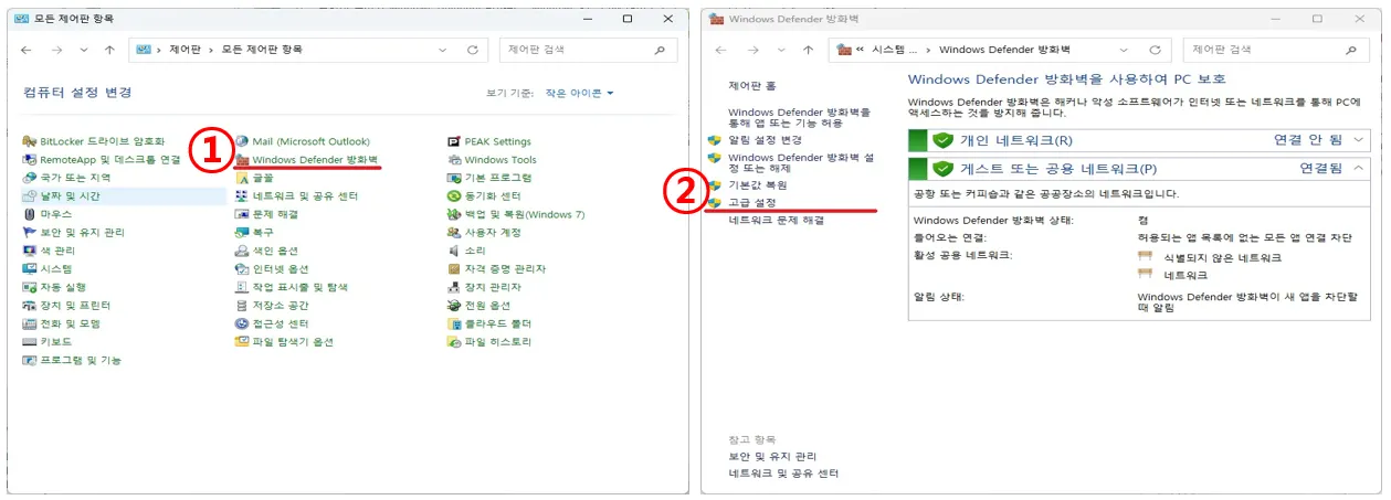
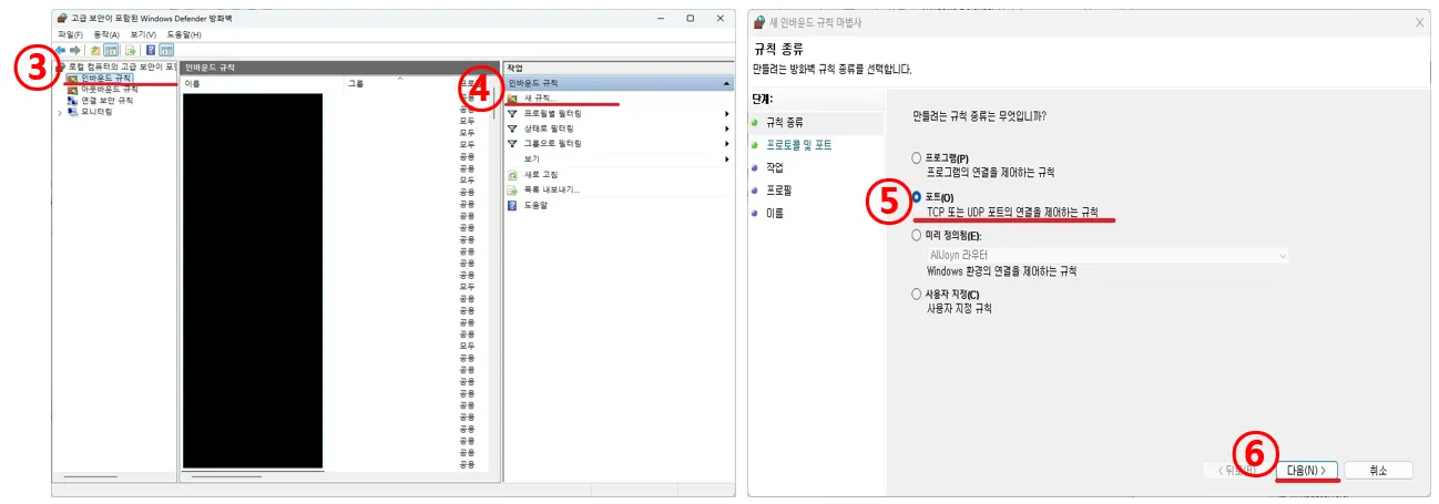
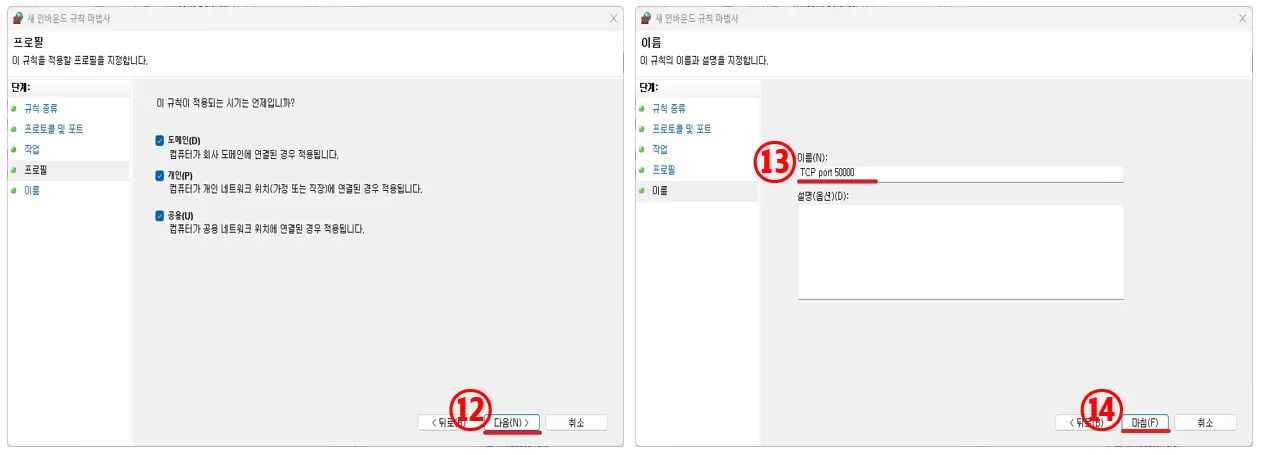
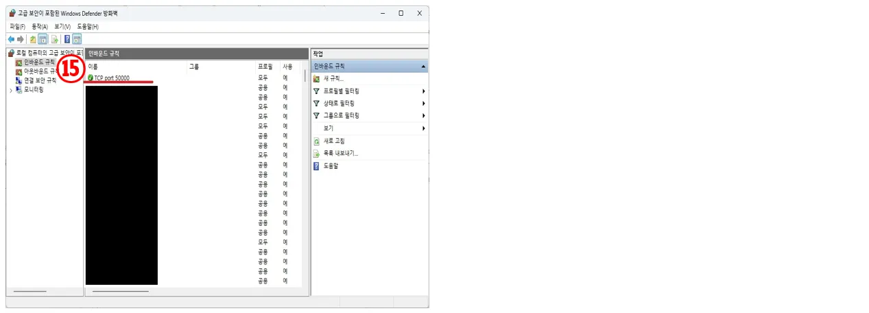
1.
Configuring the firewall to allow port 50000
Accordingly, on some PCs, it may be necessary to configure firewall settings to open the new port as shown below.
2.
TCP or UDP communication
Except for the change to port number 50000, the command descriptions remain the same as before.
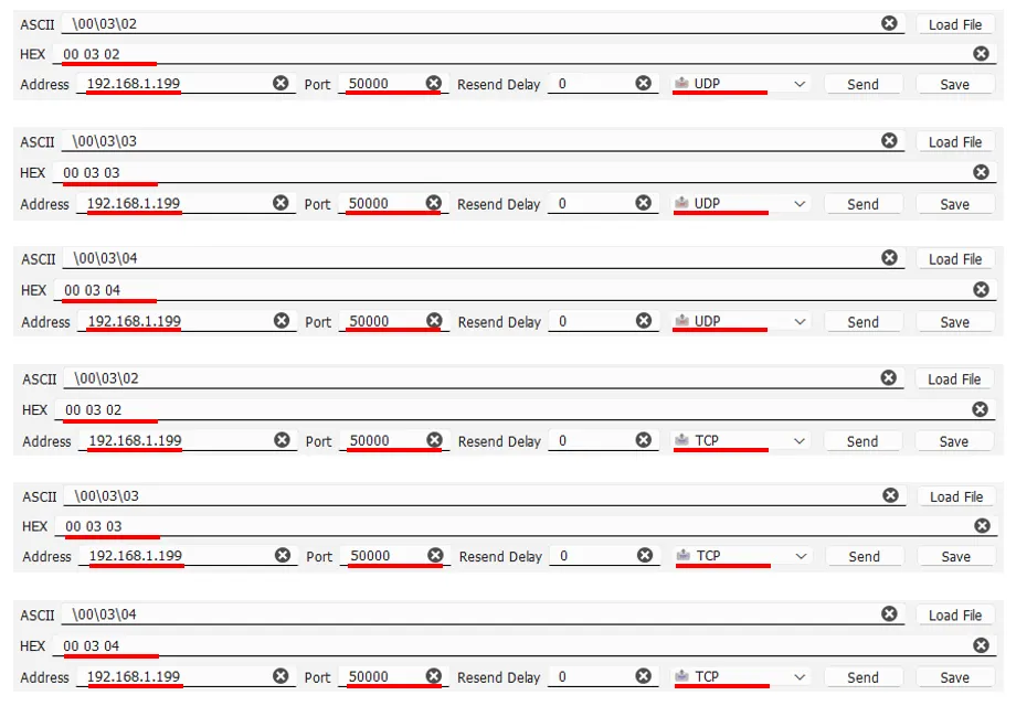
3.
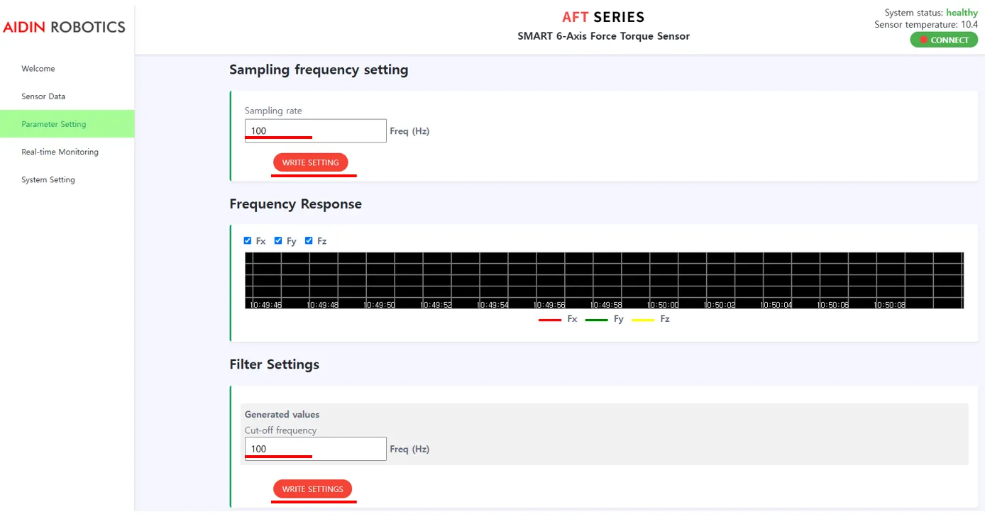
SET sampling frequency and LPF cut-off frequency
The configurable sampling frequency range is 20 Hz to 1000 Hz
The configurable cutoff frequency must satisfy 1 < freq_cutoff < 500