revision date: 2025.11.12
FOREWORD
Thank you for purchasing our Force Torque sensor. This manual contains the information
necessary for the correct use of the AIDIN ROBOTICS AFT150-D50 sensor.
Please carefully read this manual when using this software.
Please note that the basic performance of the product will not be exhibited when the robot system is used out of conditions.
This manual describes possible dangers and consequences using Force Torque sensor. Be sure
to comply with safety precautions written in this manual to use safety and correctly.
NOTICE
This manual Do NOT allow copy, reproduction or share without authorization of AIDIN ROBOTICS.
Please notify us any errors in this manual or the provided instructions.
MANUFACTURER
AIDIN ROBOTICS
SAFETY PRECAUTIONS
Installation of Force Torque sensor MUST be performed by qualified personnel in accordance with national and local codes. Please carefully read this manual when using this software.
WARNING & CAUTION
This symbol indicates that a danger of possible serious injury or death exists if the associated instructions are not followed properly.
This symbol indicates that a danger of possible harm to people or physical damage to equipment and facilities exists if the associated instructions are not followed properly.
AFT150-D50-EC sensor from AIDIN ROBOTICS meets CE-certified “A Class”
1. Introduction
1.1 Smart 6-axis Force Torque Sensor, AFT150-D50
1.2 Key features
•
Smart 6-axis force/torque sensor
•
All-in-one sensor (No additional amplifier)
•
Digital output communications (CAN, etc)
•
Easy installation and data collection
•
Grippers, robot hands, collaborative robot, industrial robot
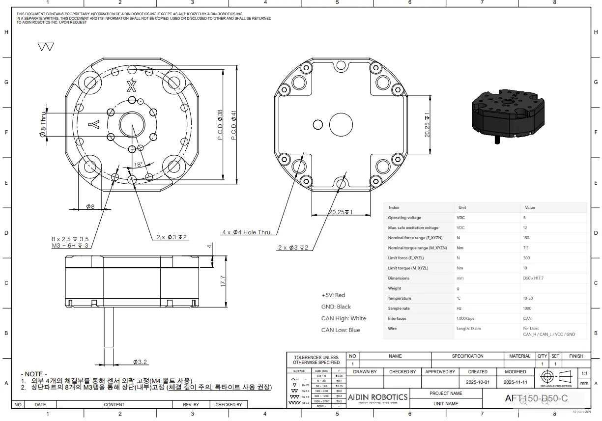
1.3 Specs.
Index | Unit | Value |
Operating voltage | VDC | 5 |
Max. safe excitation voltage | VDC | 12 |
Nominal force range (F_XYZN) | N | 150 |
Nominal torque range (M_XYZN) | Nm | 7.5 |
Limit force (F_XYZL) | N | 300 |
Limit torque (M_XYZL) | Nm | 10 |
Dimensions | mm | D50 x H17.7 |
Weight | g | 60 |
Temperature | ℃ | 10-50 |
Sample rate | Hz | 1000 |
Interfaces | 1,000Kbps | CAN |
Wire | Length: 15 cm | For User:
CAN_H / CAN_L / VCC / GND |
2. Installation Guide
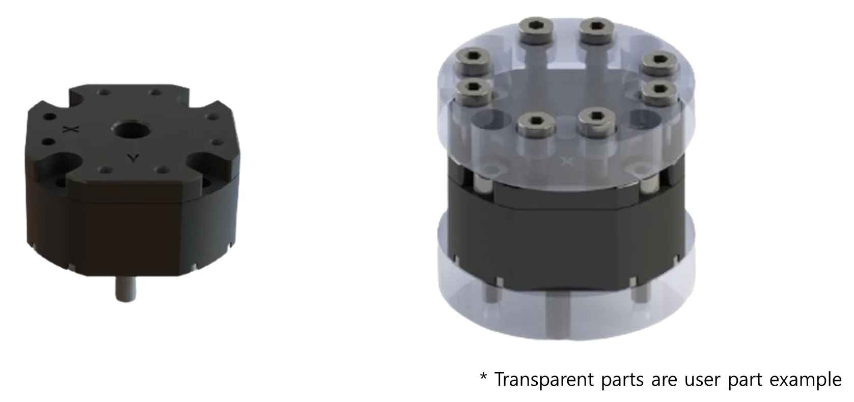
2.1 Basic Components
•
AFT150-D50 x 1 EA
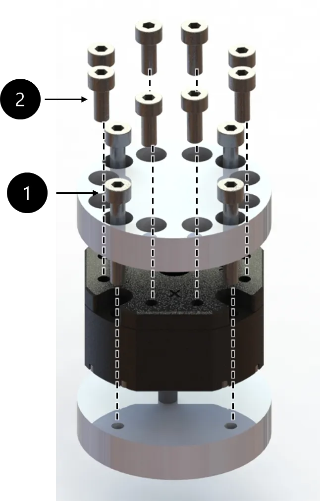
2.2 Mounting
M3 bolt 1.5Nm required for tightening (Need Locatiting)
M4 bolt 3.6Nm required for tightening
There are two types of bolts used.
•
The first type is M4 bolt, which fixes the sensor to the bottom part, requires a length of at least 12.5 mm.
•
The second type is M3 bolt, which is used for the top part that contacts the upper plate of the sensor, must not protrude more than 3 mm into the sensor.
Please take caution when assembling.
•
Performance cannot be guaranteed and A/S not possible when disassembling internal/external bolts
•
Sensor tightening order
•
CAUTION OF CABLE CUTTING AND EXCESS PULLING
•
Secure the sensor line with the robot so that it does not pull as it moves
◦
Do not fix it to the robot using cable ties, etc., or use cable ties to fix it in a bundle shape like other wires
◦
We recommend that you use Velcro to fix it with the robot, and please use Velcro to fix it when fixing it in a bundle form with other lines
Performance CANNOT be guaranteed if not followed to the tightening torque guide.
If the sensor line is not fixed to the robot, the output signal may have a noise due to the pulled by robot
2.3 AXIS & Drawings
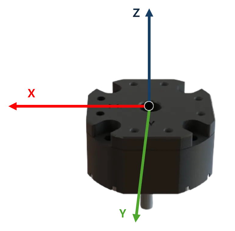
Drawing File :2.3 Wiring
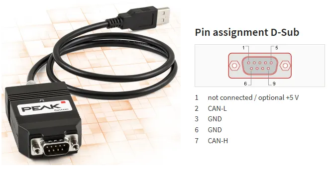
2.3.1 Cable open-end
•
Cable pin out
◦
Length: 15cm
◦
+5V: Red
◦
GND: Black
◦
CAN High: White
◦
CAN Low: Blue
2.4 Default Data Output Rate
•
The output rate can be changed from 100 Hz to 1000 Hz
•
Please refer to the “2.5 Mode setting” below for how to change it
•
CAN-2.0
◦
Nominal bitrate : 1Mbps
◦
Data bitrate : 1Mbps
◦
RX ID MASK : 0x220~0x22F, 0x320~0x32F
•
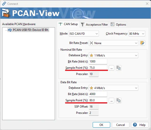
CAN-FD
◦
Nominal bitrate : 1Mbps
◦
Data bitrate : 4Mbps (BRS mode)
◦
RX ID MASK : 0x220~0x22F, 0x320~0x32F
•
PCAN : CAN-FD PARAMETER SETTING
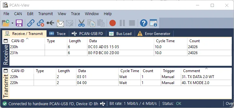
2.5 Mode setting
CAN ID | Data[0] | Data[1]~ |
0x220 or 0x320 | 0x01 | BID(Board ID) setting → Not used |
0x02 | Bias setting | |
0x03 | Trasmitting mode setting
0 : INT without temperature compensation
1 : INT with temperature compensation
2 : INT Combined without temperature compensation (FD only)
3 : INT Combined with temperature compensation (FD only)
4 : Float Combined without temperature compensation (FD only)
5 : Float Combined with temperature compensation (FD only) | |
0x04 | CAN TX mode setting
0 : CAN 2.0 mode
1 : CAN FD mode | |
0x05 | Sample rate setting
0 : RATE 100Hz
1 : RATE 250Hz
2 : RATE 500Hz
3 : RATE 1000Hz | |
0xFF | Factory Reset mode etc… |
To stabilize the sensor signal, it is recommended to have a running time of about 30 minutes.
* Please leave the sensor data on for at least 10 minutes before using it
The first 10 minutes of sensor output data can cause data to flow.
2.5.1 Force & Torque data Casting
Force INT Transmitting mode (data[0] : 0x03, data[1] : 0/1)
ID | DLC | data[0] | data[1] | data[2] | data[3] | data[4] | data[5] |
0x230- CAN 2.0 mode0x330- CAN FD mode | 6 | Fx(LSB) | Fx(MSB) | Fy(LSB) | Fy(MSB) | Fz(LSB) | Fz(MSB) |
•
Fx Output = Fx(MSB)*256 + Fx(LSB)
•
Fy Output = Fy(MSB)*256 + Fy(LSB)
•
Fz Output = Fz(MSB)*256 + Fz(LSB)
•
Force[N] = Force Output/100
The final calculated Force and Torque values need to be cast into 16-bit integers.
Torque INT Transmitting mode (data[0] : 0x03, data[1] : 0/1)
ID | DLC | data[0] | data[1] | data[2] | data[3] | data[4] | data[5] |
0x231- CAN 2.0 mode0x331- CAN FD mode | 6 | Tx(LSB) | Tx(MSB) | Ty(LSB) | Ty(MSB) | Tz(LSB) | Tz(MSB) |
•
Tx Output = Tx(MSB)*256 + Tx(LSB)
•
Ty Output = Ty(MSB)*256 + Ty(LSB)
•
Tz Output = Tz(MSB)*256 + Tz(LSB)
•
Torque[Nm] = Torque Output/1000
The final calculated Force and Torque values need to be cast into 16-bit integers.
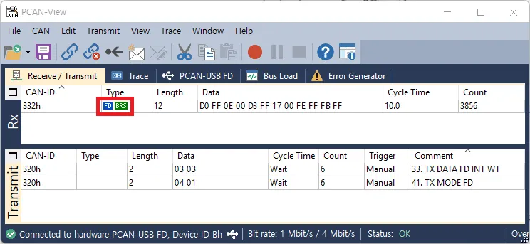
INT Combined Transmitting mode (data[0] : 0x03, data[1] : 2/3, )
ID | DLC | data[0] | data[1] | data[2] | data[3] | data[4] | data[5] | data[6] | data[7] | data[8] | data[9] | data[10] | data[11] |
0x332 | 12 | Fx(LSB) | Fx(MSB) | Fy(LSB) | Fy(MSB) | Fz(LSB) | Fz(MSB) | Tx(LSB) | Tx(MSB) | Ty(LSB) | Ty(MSB) | Tz(LSB) | Tz(MSB) |
•
Fx Output = Fx(MSB)*256 + Fx(LSB)
•
Fy Output = Fy(MSB)*256 + Fy(LSB)
•
Fz Output = Fz(MSB)*256 + Fz(LSB)
•
Tx Output = Tx(MSB)*256 + Tx(LSB)
•
Ty Output = Ty(MSB)*256 + Ty(LSB)
•
Tz Output = Tz(MSB)*256 + Tz(LSB)
•
Force[N] = Force Output/100
•
Torque[Nm] = Torque Output/1000
The final calculated Force and Torque values need to be cast into 16-bit integers
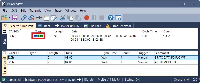
Float Combined Transmitting mode (data[0] : 0x03, data[1] : 4/5, )
ID | DLC | data[0~3] | data[4~7] | data[8~11] | data[12~15] | data[16~19] | data[20~23] |
0x332 | 24 | Fx | Fy | Fz | Tx | Ty | Tz |
•
uint32_t Fx_Raw = (Fx(MSB) << 24) | (Fx(3rd) << 16) | (Fx(2nd) << 8) | (Fx(LSB));
•
float Fx_Output = *(float *)&Fx_Raw ;
•
uint32_t Fy_Raw = (Fy(MSB) << 24) | (Fy(3rd) << 16) | (Fy(2nd) << 8) | (Fy(LSB));
•
float Fy_Output = *(float *)&Fy_Raw ;
•
uint32_t Fz_Raw = (Fz(MSB) << 24) | (Fz(3rd) << 16) | (Fz(2nd) << 8) | (Fz(LSB));
•
float Fz_Output = *(float *)&Fz_Raw ;
•
uint32_t Tx_Raw = (Tx(MSB) << 24) | (Tx(3rd) << 16) | (Tx(2nd) << 8) | (Tx(LSB));
•
float Tx_Output = *(float *)&Tx_Raw ;
•
uint32_t Ty_Raw = (Ty(MSB) << 24) | (Ty(3rd) << 16) | (Ty(2nd) << 8) | (Ty(LSB));
•
float Ty_Output = *(float *)&Ty_Raw ;
•
uint32_t Tz_Raw = (Tz(MSB) << 24) | (Tz(3rd) << 16) | (Tz(2nd) << 8) | (Tz(LSB));
•
float Tz_Output = *(float *)&Tz_Raw ;
•
Force[N] = Force Output
•
Torque[Nm] = Torque Output
The final calculated Force and Torque values need to be cast into float.
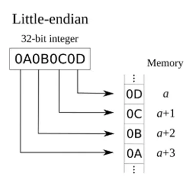
The calculation of the data must follow the little-endian format.
2.5.2 DEVICES
PCAN-USB FD Device (USB to CAN FD)
•
You may use a different CAN-enabled board, but use peak-system converter to use the sample program
•
2.6 Force/Torque Out of Range
The sensor can operate up to its nominal capacity, while a single axis load. On Nominal capacity reading is incorrect and invalid.
The nominal capacity of composite loading is The following diagram illustrates a complex loading scenario. The sensor cannot operate outside the normal operating area
The following graph shows the range of payloads and tool lengths that can be used with AFT200-D50-C sensor for applications requiring high or moderate precision.
• The total percentage of the calibrated range used by Fxy and Tz axes is greater than 105%. Refer to the following Fxy, Tz equation.
• The total percentage of the calibrated range used by Fz and Txy axes is greater than 105%. Refer to the following Fz, Txy equation.
3. Software
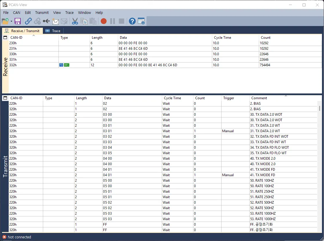
3.1.1 PCAN-View
•
pcan-view
•
Download link